Owner's guide
Page 10
... system. Each cable connector is colored gray or black and embossed with two pairs of wires connects the Acoustimass module to the left of wires to connect the Acoustimass module to identify the cube speaker, the output, or the input it matches. Figure 9 Separating cables • The... 20 foot (6 m) cable with three pairs of wires connects the Acoustimass module to the center, left front, and right front cube speakers. • The 50 foot (15 m) cable with a letter to L/R the center and front cube speakers. Bose Customer Service telephone numbers are laying out the cable lengths...
... system. Each cable connector is colored gray or black and embossed with two pairs of wires connects the Acoustimass module to the left of wires to connect the Acoustimass module to identify the cube speaker, the output, or the input it matches. Figure 9 Separating cables • The... 20 foot (6 m) cable with three pairs of wires connects the Acoustimass module to the center, left front, and right front cube speakers. • The 50 foot (15 m) cable with a letter to L/R the center and front cube speakers. Bose Customer Service telephone numbers are laying out the cable lengths...
Owner's guide
Page 11
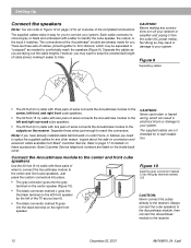
... the 20 foot (6 m) cable with five wire pairs to connect the Acoustimass module to your surround sound receiver. 1. a. LEFT wires go to the CENTER SPEAKER OUTPUT connections. RIGHT wires go to the RIGHT FRONT SPEAKER OUTPUT connections. LEFT SURROUND wires go to the LEFT SURROUND (rear) SPEAKER OUTPUT connections. RIGHT SURROUND wires go into the LS and RS OUTPUT...
... the 20 foot (6 m) cable with five wire pairs to connect the Acoustimass module to your surround sound receiver. 1. a. LEFT wires go to the CENTER SPEAKER OUTPUT connections. RIGHT wires go to the RIGHT FRONT SPEAKER OUTPUT connections. LEFT SURROUND wires go to the LEFT SURROUND (rear) SPEAKER OUTPUT connections. RIGHT SURROUND wires go into the LS and RS OUTPUT...
Owner's guide
Page 12
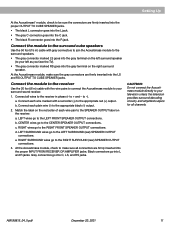
... RS LS CAUTION: Do not allow exposed wires to -). to brush against each other; this could damage your receiver in your room (Figure 12). Setting Up Check the connections Check all speakers are connected as front speakers (Figure 11). At the receiver, make sure the wires are connected in a total loss of Acoustimass module output.
... RS LS CAUTION: Do not allow exposed wires to -). to brush against each other; this could damage your receiver in your room (Figure 12). Setting Up Check the connections Check all speakers are connected as front speakers (Figure 11). At the receiver, make sure the wires are connected in a total loss of Acoustimass module output.
Owner's guide
Page 17
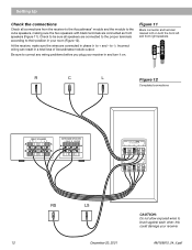
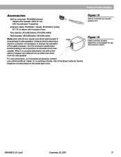
... cover. Cable For more information, or to change the orientation of the cube speaker. Or, to call Bose directly, refer to cube speaker for use with Acoustimass®-6 speakers Extension cable: PN187092-1 (black), PN187092-2 (white) 50' (15 m) ribbon with five pairs of wire Floor stands: UFS-20B (black), UFS-20W (white) Wall brackets: UB-20B (black...
... cover. Cable For more information, or to change the orientation of the cube speaker. Or, to call Bose directly, refer to cube speaker for use with Acoustimass®-6 speakers Extension cable: PN187092-1 (black), PN187092-2 (white) 50' (15 m) ribbon with five pairs of wire Floor stands: UFS-20B (black), UFS-20W (white) Wall brackets: UB-20B (black...


