Owner's guide
Page 8
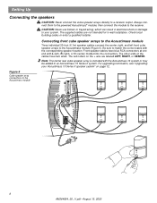
...speaker cables have two wires. The red collars on page 12. Check local building codes or enlist a qualified installer. The other ends of the cables have blue RCA connectors at one end with the Acoustimass 16 system or may be added to the Acoustimass module (Figure 5). ...Connecting front cube speaker arrays to the Acoustimass module Three individual 20-foot (6.1m) speaker cables connect the center, right, and left ), ...
...speaker cables have two wires. The red collars on page 12. Check local building codes or enlist a qualified installer. The other ends of the cables have blue RCA connectors at one end with the Acoustimass 16 system or may be added to the Acoustimass module (Figure 5). ...Connecting front cube speaker arrays to the Acoustimass module Three individual 20-foot (6.1m) speaker cables connect the center, right, and left ), ...
Owner's guide
Page 9
... CENTER REAR. 1. Connect the wire pair marked RIGHT to the right front cube speaker array (to the left rear cube speaker array. 3. Connect the wire pair marked LEFT to the right of the cables have a center rear cube speaker array (Acoustimass 16 system or upgraded Acoustimass 15 Series II system), connect... the wire pair marked CENTER REAR to secure the wires. 2. Plug the other ends of the TV as you face the TV). Release the tab...
... CENTER REAR. 1. Connect the wire pair marked RIGHT to the right front cube speaker array (to the left rear cube speaker array. 3. Connect the wire pair marked LEFT to the right of the cables have a center rear cube speaker array (Acoustimass 16 system or upgraded Acoustimass 15 Series II system), connect... the wire pair marked CENTER REAR to secure the wires. 2. Plug the other ends of the TV as you face the TV). Release the tab...
Owner's guide
Page 10
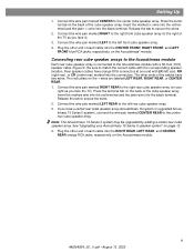
...multi-pin connector on one end and several wire pairs on your receiver and unplug it provides surround decoding circuitry and amplified outputs for connection to the LFE/SUBWOOFER OUT jack. Each wire pair is marked on the Acoustimass module. CAUTION: Before making any connections ...turn off your surround receiver. terminal. If your system. CAUTION: Do not allow exposed wires to brush against each wire connects to the receiver. Insert the multi-...
...multi-pin connector on one end and several wire pairs on your receiver and unplug it provides surround decoding circuitry and amplified outputs for connection to the LFE/SUBWOOFER OUT jack. Each wire pair is marked on the Acoustimass module. CAUTION: Before making any connections ...turn off your surround receiver. terminal. If your system. CAUTION: Do not allow exposed wires to brush against each wire connects to the receiver. Insert the multi-...
Owner's guide
Page 12
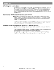
Setting Up Checking the connections Check all connections from the receiver to the Acoustimass® module and from your system. Incorrect wiring can eliminate the vast majority of module output. Correct wiring problems before you with your surround receiver. A quality suppressor can result ...cable, and complete connection instructions. See the list of Bose offices and phone numbers enclosed with 6.1 or 6 channel surround sound. Connecting the Acoustimass module to know the serial number of the powered Acoustimass module into an AC (mains) receptacle. Voltage variations...
Setting Up Checking the connections Check all connections from the receiver to the Acoustimass® module and from your system. Incorrect wiring can eliminate the vast majority of module output. Correct wiring problems before you with your surround receiver. A quality suppressor can result ...cable, and complete connection instructions. See the list of Bose offices and phone numbers enclosed with 6.1 or 6 channel surround sound. Connecting the Acoustimass module to know the serial number of the powered Acoustimass module into an AC (mains) receptacle. Voltage variations...
Owner's guide
Page 15
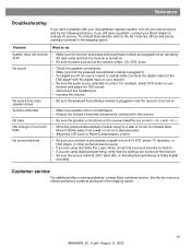
... your receiver is turned on . Reference Troubleshooting If you have a problem, contact your Bose® dealer to -). Problem What to do System does not function • Make sure the receiver and powered Acoustimass module are correct (+ to decrease bass. • Adjust the LFE Level or Room Compensation...Make sure that the receiver is processing a signal from a wall or corner to + and - Sound is distorted • Make sure speaker wire is plugged in the shipping carton. 15 AM264924_00 _V.pdf • August 13, 2002 See the list of service offices and phone ...
... your receiver is turned on . Reference Troubleshooting If you have a problem, contact your Bose® dealer to -). Problem What to do System does not function • Make sure the receiver and powered Acoustimass module are correct (+ to decrease bass. • Adjust the LFE Level or Room Compensation...Make sure that the receiver is processing a signal from a wall or corner to + and - Sound is distorted • Make sure speaker wire is plugged in the shipping carton. 15 AM264924_00 _V.pdf • August 13, 2002 See the list of service offices and phone ...
Owner's guide
Page 17
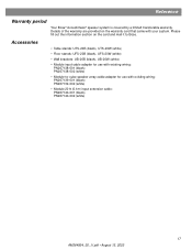
Please fill out the information section on the warranty card that came with your system. Reference Warranty period Your Bose® Acoustimass® speaker system is covered by a limited transferable warranty. Details of the warranty are provided on the card and mail it to -cube speaker array ... stands: UFS-20B (black), UFS-20W (white) • Wall brackets: UB-20B (black), UB-20W (white) • Module input cable adapter for use with existing wiring: PN267138-001 (black) PN267138-002 (white) • Module-to...
Please fill out the information section on the warranty card that came with your system. Reference Warranty period Your Bose® Acoustimass® speaker system is covered by a limited transferable warranty. Details of the warranty are provided on the card and mail it to -cube speaker array ... stands: UFS-20B (black), UFS-20W (white) • Wall brackets: UB-20B (black), UB-20W (white) • Module input cable adapter for use with existing wiring: PN267138-001 (black) PN267138-002 (white) • Module-to...


