
Owner's guide
Page 8
... foot (6 m) cable with three pairs of wires connects the Acoustimass module to the center, left, and right front cube speakers. • The 50 foot (15 m) cable with two pairs of wires connects the Acoustimass module to the left surround speaker. • The gray connector marked RS goes...to the right surround speaker. Never use standard RCA cables to colored RCA connectors. Call Bose® customer service for cables specifically designed for you in -wall installation. Always connect the cube speakers to the Acoustimass module, then connect the Acoustimass module to an receiver ...
... foot (6 m) cable with three pairs of wires connects the Acoustimass module to the center, left, and right front cube speakers. • The 50 foot (15 m) cable with two pairs of wires connects the Acoustimass module to the left surround speaker. • The gray connector marked RS goes...to the right surround speaker. Never use standard RCA cables to colored RCA connectors. Call Bose® customer service for cables specifically designed for you in -wall installation. Always connect the cube speakers to the Acoustimass module, then connect the Acoustimass module to an receiver ...

Owner's guide
Page 9
... you face it), and the black connector marked R to the black terminal on the center speaker. 2. c. R wires go to the Left Surround (rear) SPEAKER OUTPUT connections. Match the polarity on the receiver: a. to the R jack. At the Acoustimass module, check to make sure the gray connectors are firmly inserted into the proper OUTPUT TO...
... you face it), and the black connector marked R to the black terminal on the center speaker. 2. c. R wires go to the Left Surround (rear) SPEAKER OUTPUT connections. Match the polarity on the receiver: a. to the R jack. At the Acoustimass module, check to make sure the gray connectors are firmly inserted into the proper OUTPUT TO...

Owner's guide
Page 10
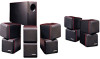
... RECEIVER OR AMPLIFIER L C R LS RS 10 December 20, 2001 AM183644_01_V.pdf Setting Up Check the connections Check all speakers are connected to the proper terminals according to brush against each other; to the cube speakers (Figure 9). CAUTION: Do not allow exposed wires to their position in a total loss of Acoustimass module output. Make sure all...
... RECEIVER OR AMPLIFIER L C R LS RS 10 December 20, 2001 AM183644_01_V.pdf Setting Up Check the connections Check all speakers are connected to the proper terminals according to brush against each other; to the cube speakers (Figure 9). CAUTION: Do not allow exposed wires to their position in a total loss of Acoustimass module output. Make sure all...


