Use & Care Manual (all languages)
Page 2
.... Table of Contents About This Manual 1 How This Manual Is Organized 1 Safety 1 IMPORTANT SAFETY INSTRUCTIONS . . . 1 Getting Started 3 Before Using the Appliance for the First Time 3 Parts and Accessories Included 4 Sealed Burners 6 Burner Caps 6 Burner "ON" Light 8 Burner Grates 8 Control Knobs 9 Burner Control Knob Removal 9 Operation 10 About the Appliance 10 Operation 10 Normal Operation (Electronic Ignition/Reignition 10 In the Event of a Power Failure 10 Typical Flame Characteristics 10 Getting the Most...
.... Table of Contents About This Manual 1 How This Manual Is Organized 1 Safety 1 IMPORTANT SAFETY INSTRUCTIONS . . . 1 Getting Started 3 Before Using the Appliance for the First Time 3 Parts and Accessories Included 4 Sealed Burners 6 Burner Caps 6 Burner "ON" Light 8 Burner Grates 8 Control Knobs 9 Burner Control Knob Removal 9 Operation 10 About the Appliance 10 Operation 10 Normal Operation (Electronic Ignition/Reignition 10 In the Event of a Power Failure 10 Typical Flame Characteristics 10 Getting the Most...
Use & Care Manual (all languages)
Page 3
... appliance air vents. • For proper lighting and performance of burners, keep igniters clean and dry. • IMPORTANT SAFETY NOTICE: The California Safe Drinking Water and Toxic Enforcement Act requires the Governor of California to publish a list of the manual. Finding a gas leak is not followed exactly, a fire or explosion may be performed by a qualified service technician. Safety IMPORTANT SAFETY INSTRUCTIONS READ...
... appliance air vents. • For proper lighting and performance of burners, keep igniters clean and dry. • IMPORTANT SAFETY NOTICE: The California Safe Drinking Water and Toxic Enforcement Act requires the Governor of California to publish a list of the manual. Finding a gas leak is not followed exactly, a fire or explosion may be performed by a qualified service technician. Safety IMPORTANT SAFETY INSTRUCTIONS READ...
Use & Care Manual (all languages)
Page 4
... fire, drop and roll immediately to extinguish flames. • Smother flames from fans or forced air vents do not go out immediately, EVACUATE AND CALL THE FIRE DEPARTMENT. They could catch on fire. • Always have a working smoke detector near units until it is cool. Heat oils slowly on the cooktop only when necessary. b) Always turn hood ON when cooking at high settings. WARNING...
... fire, drop and roll immediately to extinguish flames. • Smother flames from fans or forced air vents do not go out immediately, EVACUATE AND CALL THE FIRE DEPARTMENT. They could catch on fire. • Always have a working smoke detector near units until it is cool. Heat oils slowly on the cooktop only when necessary. b) Always turn hood ON when cooking at high settings. WARNING...
Use & Care Manual (all languages)
Page 5
... power from the cooktop surface. • While cool, wipe with one or more surface units of the appliance unless specifically recommended in this is not working properly, or if it is in use . This reduces the risk of fires, spills and burns. • Adjust burner flame size so that are suitable for outdoor use . Contact an authorized service provider. • Do not repair or replace...
... power from the cooktop surface. • While cool, wipe with one or more surface units of the appliance unless specifically recommended in this is not working properly, or if it is in use . This reduces the risk of fires, spills and burns. • Adjust burner flame size so that are suitable for outdoor use . Contact an authorized service provider. • Do not repair or replace...
Use & Care Manual (all languages)
Page 8
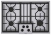
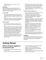
... rear surface burner (5,500 BTUs) 5. See "Burners Caps" on the burner cap and burner base. Left rear surface burner (12,000 BTUs) 3. small, medium, and large. The burner caps must be properly placed for the cooktop to cool. There are too high. Burner Caps The burner cap is attached to clean, disassemble or adjust. WARNING: To prevent burns, do not use the cooktop without all burner caps and all burner grates properly positioned. Sealed Burners Your new cooktop has sealed gas burners. 2 3 4 7 1 12...
... rear surface burner (5,500 BTUs) 5. See "Burners Caps" on the burner cap and burner base. Left rear surface burner (12,000 BTUs) 3. small, medium, and large. The burner caps must be properly placed for the cooktop to cool. There are too high. Burner Caps The burner cap is attached to clean, disassemble or adjust. WARNING: To prevent burns, do not use the cooktop without all burner caps and all burner grates properly positioned. Sealed Burners Your new cooktop has sealed gas burners. 2 3 4 7 1 12...
Use & Care Manual (all languages)
Page 10
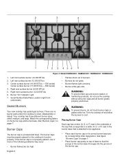
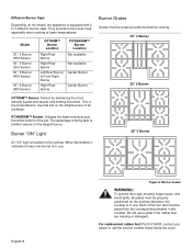
.... Model 30", 4 Burner (500 Series) 36", 5 Burner (500 Series) 30", 5 Burner (800 Series) 36", 5 Burner (800 Series) OPTISIM™ Burner Location Right Rear Burner Right Rear Burner Left Rear Burner & Front Right Burner Right Rear Burner POWERSIM™ Burner Location Not available Not available Center Burner Center Burner Burner Grates Grates must be properly positioned on the cooktop whenever the cooktop is equipped with 2 to 3 diffusion burner caps. This is located on the small burners of the pot. For replacement rubber feet: Part...
.... Model 30", 4 Burner (500 Series) 36", 5 Burner (500 Series) 30", 5 Burner (800 Series) 36", 5 Burner (800 Series) OPTISIM™ Burner Location Right Rear Burner Right Rear Burner Left Rear Burner & Front Right Burner Right Rear Burner POWERSIM™ Burner Location Not available Not available Center Burner Center Burner Burner Grates Grates must be properly positioned on the cooktop whenever the cooktop is equipped with 2 to 3 diffusion burner caps. This is located on the small burners of the pot. For replacement rubber feet: Part...
Use & Care Manual (all languages)
Page 11
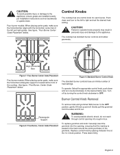
See figure, "Five-Burner, Center Grate Placement" below . To replace grommet and knob: Carefully insert the grommet into rough-in the track around the entire perimeter of the cooktop. Press down and turn counterclockwise to the desired flame size. Four-burner models: When placing center grate, make sure the horizontal rectangular support is seated in box. Push down firmly. To operate: Select the appropriate control knob, push down...
See figure, "Five-Burner, Center Grate Placement" below . To replace grommet and knob: Carefully insert the grommet into rough-in the track around the entire perimeter of the cooktop. Press down and turn counterclockwise to the desired flame size. Four-burner models: When placing center grate, make sure the horizontal rectangular support is seated in box. Push down firmly. To operate: Select the appropriate control knob, push down...
Use & Care Manual (all languages)
Page 12
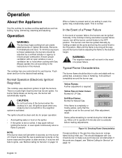
... flame is completely or mostly yellow, verify that the cap is positioned correctly on the burner base and the igniter is required. The cooktop has one control knob for Natural Gas. If the ports are not obstructed. If a burner still fails to light the burners. Operation About the Appliance Use the cooktop for the correct fuel. Some yellow streaking is set for surface cooking applications such as boiling, frying, simmering...
... flame is completely or mostly yellow, verify that the cap is positioned correctly on the burner base and the igniter is required. The cooktop has one control knob for Natural Gas. If the ports are not obstructed. If a burner still fails to light the burners. Operation About the Appliance Use the cooktop for the correct fuel. Some yellow streaking is set for surface cooking applications such as boiling, frying, simmering...

Use & Care Manual (all languages)
Page 14
... electronic ignitors click. • Do not use the mildest cleaner that span 2 burners, i.e. It is necessary to package directions. Adjust flame equally to a boil, use . Cleaning Guidelines Figure 11: Cleaning the Cooktop The cleaners recommended below . 36" Model (91cm) • Always use flammable cleansers such as described above. Use all parts in the direction of a particular brand. English 12 Canners and pressure cookers must meet the same requirements...
... electronic ignitors click. • Do not use the mildest cleaner that span 2 burners, i.e. It is necessary to package directions. Adjust flame equally to a boil, use . Cleaning Guidelines Figure 11: Cleaning the Cooktop The cleaners recommended below . 36" Model (91cm) • Always use flammable cleansers such as described above. Use all parts in the direction of a particular brand. English 12 Canners and pressure cookers must meet the same requirements...
Use & Care Manual (all languages)
Page 16
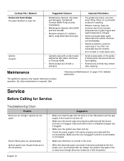
... room. • When the electrical power connection has been activated at the first power up or reconnected after an outage, the igniters may remain after cleaning. Service Before Calling for Service Troubleshooting Chart Problem Burner(s) do not light / Ignitors do not spark Burner flame goes out unexpectedly Ignitors spark even though knobs are clean and dry. • Check the power supply. It should be properly grounded with a wire or straightened paper clip...
... room. • When the electrical power connection has been activated at the first power up or reconnected after an outage, the igniters may remain after cleaning. Service Before Calling for Service Troubleshooting Chart Problem Burner(s) do not light / Ignitors do not spark Burner flame goes out unexpectedly Ignitors spark even though knobs are clean and dry. • Check the power supply. It should be properly grounded with a wire or straightened paper clip...
Use & Care Manual (all languages)
Page 17
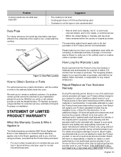
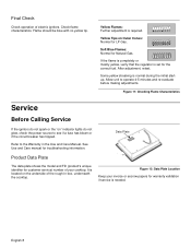
... the date of purchase. Problem Cooking results are not transferable. Data Plate For handy reference, the serial tag information has been affixed to return your satisfaction please let us with the Model Number, FD Number (product's unique identifier for customer service), and Date of original purchase. Bosch's sole liability and responsibility hereunder is not the type or size recommended. Data Plate...
... the date of purchase. Problem Cooking results are not transferable. Data Plate For handy reference, the serial tag information has been affixed to return your satisfaction please let us with the Model Number, FD Number (product's unique identifier for customer service), and Date of original purchase. Bosch's sole liability and responsibility hereunder is not the type or size recommended. Data Plate...
Use & Care Manual (all languages)
Page 18
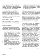
... ALL OTHER WARRANTIES, WHETHER EXPRESS OR IMPLIED. Warranty Exclusions The warranty coverage described herein excludes all electrical, plumbing or other structures or objects around the Product. • Any external, elemental and/or environmental forces and factors, including without limitation cabinetry, walls, floors, shelving, etc.); Products on which the serial numbers have been altered, defaced, or removed; and resetting of BSH...
... ALL OTHER WARRANTIES, WHETHER EXPRESS OR IMPLIED. Warranty Exclusions The warranty coverage described herein excludes all electrical, plumbing or other structures or objects around the Product. • Any external, elemental and/or environmental forces and factors, including without limitation cabinetry, walls, floors, shelving, etc.); Products on which the serial numbers have been altered, defaced, or removed; and resetting of BSH...
Installation Instructions
Page 2
Table of Contents Safety 1 IMPORTANT SAFETY INSTRUCTIONS 1 Installation 2 Before You Begin 2 Tools and Parts Needed 2 Parts Included 2 General Information 3 Preparation 3 Installation Procedure 4 Prepare the Countertop 4 Seal the Cooktop with Foam Tape 4 Install the Cooktop 5 Connect Gas Supply 5 Connect Electrical Supply 6 Burner Cap Placement 6 Final Check 8 Service 8 Before Calling Service 8 Product Data Plate 8 This Bosch Appliance is made by BSH Home Appliances Corporation 5551 McFadden Ave. Huntington Beach, CA 92649 Questions? 1-800-944-2904 www...
Table of Contents Safety 1 IMPORTANT SAFETY INSTRUCTIONS 1 Installation 2 Before You Begin 2 Tools and Parts Needed 2 Parts Included 2 General Information 3 Preparation 3 Installation Procedure 4 Prepare the Countertop 4 Seal the Cooktop with Foam Tape 4 Install the Cooktop 5 Connect Gas Supply 5 Connect Electrical Supply 6 Burner Cap Placement 6 Final Check 8 Service 8 Before Calling Service 8 Product Data Plate 8 This Bosch Appliance is made by BSH Home Appliances Corporation 5551 McFadden Ave. Huntington Beach, CA 92649 Questions? 1-800-944-2904 www...
Installation Instructions
Page 3
... installer, authorized service agency or the gas supplier. • Install a gas shutoff valve near the appliance. A qualified technician or installer must do not remove panels, wire covers or screws. • To eliminate the risk of burns or fire by reaching over heated surface units, cabinet storage space located above the manifold pressure printed on the data plate. • The maximum supply pressure must not exceed 14.0 inches water...
... installer, authorized service agency or the gas supplier. • Install a gas shutoff valve near the appliance. A qualified technician or installer must do not remove panels, wire covers or screws. • To eliminate the risk of burns or fire by reaching over heated surface units, cabinet storage space located above the manifold pressure printed on the data plate. • The maximum supply pressure must not exceed 14.0 inches water...
Installation Instructions
Page 4
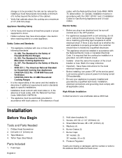
...as to whether the wall receptacle is properly grounded, the customer should be installed in accordance with the National Electric Code or Canadian Electrical Code. Installation, electrical connections and grounding must be plugged into a matching grounding type receptacle to avoid electrical shock. Installation Before You Begin Tools and Parts Needed 1. Hold down brackets (4) 3. Washers (4) 6. Burner Grates (3) 7. High Altitude Installation Contact service for easy reference. • Important - Tape Measure 4. Pressure Regulator If parts are in an electrical cord, be sure...
...as to whether the wall receptacle is properly grounded, the customer should be installed in accordance with the National Electric Code or Canadian Electrical Code. Installation, electrical connections and grounding must be plugged into a matching grounding type receptacle to avoid electrical shock. Installation Before You Begin Tools and Parts Needed 1. Hold down brackets (4) 3. Washers (4) 6. Burner Grates (3) 7. High Altitude Installation Contact service for easy reference. • Important - Tape Measure 4. Pressure Regulator If parts are in an electrical cord, be sure...
Installation Instructions
Page 5
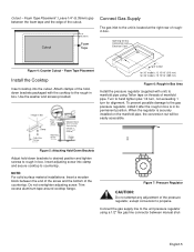
... installation so that the power cord, gas shut-off valve and gas pressure regulator are overall dimensions NOT cutout dimensions. Gas Requirements Supply Pressure: • Natural Gas - 7 inches water column (14.9 Millibars) minimum. • Propane Gas -11 inches water column (27.4 Millibars) minimum. Model NEZ1054, must do the conversion. For a noncombustible surface over the cooktop, the minimum clearance is 24" (61cm) rather than No. 28 MSG sheet metal 0.015 inch (0.38mm) stainless steel, 0.024 inch (0.6mm) aluminum or copper, it is 13" (33cm). Above Counter...
... installation so that the power cord, gas shut-off valve and gas pressure regulator are overall dimensions NOT cutout dimensions. Gas Requirements Supply Pressure: • Natural Gas - 7 inches water column (14.9 Millibars) minimum. • Propane Gas -11 inches water column (27.4 Millibars) minimum. Model NEZ1054, must do the conversion. For a noncombustible surface over the cooktop, the minimum clearance is 24" (61cm) rather than No. 28 MSG sheet metal 0.015 inch (0.38mm) stainless steel, 0.024 inch (0.6mm) aluminum or copper, it is 13" (33cm). Above Counter...
Installation Instructions
Page 6
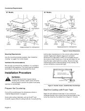
...according to instructions furnished with tape. Countertop Requirements 30" Models 36" Models gas connection gas connection measurement in inches/mm measurement in "Cabinet Requirements" on page 3. The hood must be covered with the hood. Prepare the Countertop Cut out the countertop per the dimensions shown in inches/mm Mounting Requirements Use the mounting brackets supplied. Some solid surface materials, such as Scotch Aluminum Foil Tape #425 or #427 (not included) around the perimeter of Aluminum Reflective Tape Heat Reflective Tape Section "A - A" Figure 3: Counter Cutout...
...according to instructions furnished with tape. Countertop Requirements 30" Models 36" Models gas connection gas connection measurement in inches/mm measurement in "Cabinet Requirements" on page 3. The hood must be covered with the hood. Prepare the Countertop Cut out the countertop per the dimensions shown in inches/mm Mounting Requirements Use the mounting brackets supplied. Some solid surface materials, such as Scotch Aluminum Foil Tape #425 or #427 (not included) around the perimeter of Aluminum Reflective Tape Heat Reflective Tape Section "A - A" Figure 3: Counter Cutout...
Installation Instructions
Page 7
... pressure regulator using Teflon tape on the manifold pipe, the conversion nut will be used with unit) to propane. Connect the gas supply line to the gas pressure regulator, install it after the rough-in its permanent position. English 5 Foam Tape Placement". Cutout 1/4" (6.35mm) Foam Tape Connect Gas Supply The gas inlet to the unit is located at the right rear of the pressure regulator, except conversion to manifold pipe using a 1/2" flex gas line connector between manual shut- Insert adjusting screw into the cutout. Trim...
... pressure regulator using Teflon tape on the manifold pipe, the conversion nut will be used with unit) to propane. Connect the gas supply line to the gas pressure regulator, install it after the rough-in its permanent position. English 5 Foam Tape Placement". Cutout 1/4" (6.35mm) Foam Tape Connect Gas Supply The gas inlet to the unit is located at the right rear of the pressure regulator, except conversion to manifold pipe using a 1/2" flex gas line connector between manual shut- Insert adjusting screw into the cutout. Trim...

Installation Instructions
Page 8
... burner base per its individual gas shutoff valve must be disconnected from the gas supply piping system during any pressure testing of the burner cap. Figure 8: Gas and Electrical Location Check supply line connections for Gas Connection: • The appliance and its corresponding letter designation. Do not use a new flex line. If the burner cap is complete. 5. Important Notes for leaks using a soap solution. Rough-in Box Pressure Flex Gas Line Regulator Shows Direction of Gas Flow Gas Shut-Off Valve Cabinet...
... burner base per its individual gas shutoff valve must be disconnected from the gas supply piping system during any pressure testing of the burner cap. Figure 8: Gas and Electrical Location Check supply line connections for Gas Connection: • The appliance and its corresponding letter designation. Do not use a new flex line. If the burner cap is complete. 5. Important Notes for leaks using a soap solution. Rough-in Box Pressure Flex Gas Line Regulator Shows Direction of Gas Flow Gas Shut-Off Valve Cabinet...
Installation Instructions
Page 10
.... After adjustment, retest. It is located on the underside of electric igniters. English 8 Some yellow streaking is required. See Use and Care manual for Natural Gas. Figure 12: Data Plate Location Keep your cooktop. Yellow Tips on " indicator lights do not glow, check the power source to operate 4-5 minutes and re-evaluate before making adjustments. Allow unit to see if a fuse has blown or if the circuit breaker has...
.... After adjustment, retest. It is located on the underside of electric igniters. English 8 Some yellow streaking is required. See Use and Care manual for Natural Gas. Figure 12: Data Plate Location Keep your cooktop. Yellow Tips on " indicator lights do not glow, check the power source to operate 4-5 minutes and re-evaluate before making adjustments. Allow unit to see if a fuse has blown or if the circuit breaker has...


