
Installation Instructions
Page 3
...Install anti-tip device packaged with all controls are engaged. Save these instructions for guidance. Injury to this manual for the local electrical inspector's use with ranges" shall be used. • Installer - Improper installation, service or maintenance can tip. Refer to persons could result. Remove...• This appliance complies with one or more of the following Standards: UL 858, The Standard for the Safety of Household Electric Ranges UL 923, The Standard for the Safety of Microwave Cooking Appliances UL 507, The Standard for easier handling and installation. It ...
...Install anti-tip device packaged with all controls are engaged. Save these instructions for guidance. Injury to this manual for the local electrical inspector's use with ranges" shall be used. • Installer - Improper installation, service or maintenance can tip. Refer to persons could result. Remove...• This appliance complies with one or more of the following Standards: UL 858, The Standard for the Safety of Household Electric Ranges UL 923, The Standard for the Safety of Microwave Cooking Appliances UL 507, The Standard for easier handling and installation. It ...

Installation Instructions
Page 5
... installed with a power cord set (not supplied).1 The electrical rating of cloth under the range to protect floors. Check the data plate for Canadian installations English 3 Reference the kW rating in Use and Care manual). Check local codes. 40... and easier to handle remove door (see instructions in the table below to keep it from the factory with Ranges." Note: In Canada, the range is shipped from opening while installing the range. Table 2: Electrical Specifications kW Rating Hz Amps Req'd 120/240V 120/208V 13 9.8 60 13.8 10.4 60 a. Variance may ...
... installed with a power cord set (not supplied).1 The electrical rating of cloth under the range to protect floors. Check the data plate for Canadian installations English 3 Reference the kW rating in Use and Care manual). Check local codes. 40... and easier to handle remove door (see instructions in the table below to keep it from the factory with Ranges." Note: In Canada, the range is shipped from opening while installing the range. Table 2: Electrical Specifications kW Rating Hz Amps Req'd 120/240V 120/208V 13 9.8 60 13.8 10.4 60 a. Variance may ...

Installation Instructions
Page 6
... space in your home is preferred. The range requires a minimum of combustible materials. This unit is designed for proper amperage ratings.A four wire connection is adequate. The electrical outlet must be increased to handle the electrical load demanded by licensed electricians. English 4...wiring inside house is adequate Contact your local utility company to verify that the present electric service to your region. Cabinet Requirements 7 1/2" (190.5 mm) 4 1/2" (114.3 mm) 3 1/2" (88.9 mm) 21" (533.4 mm) 30" (762 mm) 4 1/2" (114.3 mm) Figure 1: Cooktop Clearances Verify that...
... space in your home is preferred. The range requires a minimum of combustible materials. This unit is designed for proper amperage ratings.A four wire connection is adequate. The electrical outlet must be increased to handle the electrical load demanded by licensed electricians. English 4...wiring inside house is adequate Contact your local utility company to verify that the present electric service to your region. Cabinet Requirements 7 1/2" (190.5 mm) 4 1/2" (114.3 mm) 3 1/2" (88.9 mm) 21" (533.4 mm) 30" (762 mm) 4 1/2" (114.3 mm) Figure 1: Cooktop Clearances Verify that...

Installation Instructions
Page 7
Replacing a Free-Standing Model 1.In Canada, a clearance of 30 inches between cabinets where range is to cabinet is required. In this case, verify that the opening is at least 30 inches.1 30" (76.2 cm) min. Allow a minimum of 12 mm from range sidewall to be installed1. See Figure 2: Cutout Requirements for more information.. 23 1/16" (585.4 mm) 30" (762 mm) Figure 2: Cutout Requirements Note: The slide-in range can also replace a freestanding range. English 5 Figure 3: Cutout Requirements -
Replacing a Free-Standing Model 1.In Canada, a clearance of 30 inches between cabinets where range is to cabinet is required. In this case, verify that the opening is at least 30 inches.1 30" (76.2 cm) min. Allow a minimum of 12 mm from range sidewall to be installed1. See Figure 2: Cutout Requirements for more information.. 23 1/16" (585.4 mm) 30" (762 mm) Figure 2: Cutout Requirements Note: The slide-in range can also replace a freestanding range. English 5 Figure 3: Cutout Requirements -

Installation Instructions
Page 8
...cabinets may discolor or stain. Install Anti-Tip Bracket 1.Instructions were determined using standard American cabinets. 4" (10.2 cm) min. 30" (76.2 cm) min. centered 30" (76.2 cm) min. 4" (10.2 cm) min. No clearance is protected by U.L., particularly self-cleaning ovens; Cabinets over...cabinets adjacent to adjacent materials: See Figure 4: Cabinet Preparation. Prepare Walls and Floor Seal any obstructions (extra electrical or gas connections, etc.) so that range will rest against wall properly. Countertops must be smooth and level. Remove any holes in Canada) Figure ...
...cabinets may discolor or stain. Install Anti-Tip Bracket 1.Instructions were determined using standard American cabinets. 4" (10.2 cm) min. 30" (76.2 cm) min. centered 30" (76.2 cm) min. 4" (10.2 cm) min. No clearance is protected by U.L., particularly self-cleaning ovens; Cabinets over...cabinets adjacent to adjacent materials: See Figure 4: Cabinet Preparation. Prepare Walls and Floor Seal any obstructions (extra electrical or gas connections, etc.) so that range will rest against wall properly. Countertops must be smooth and level. Remove any holes in Canada) Figure ...

Installation Instructions
Page 9
...to instructions furnished with 2 screws adequate for mounting surface (i.e., for wood floor use wood screws, for more information English 7 The range hood must be installed according to center of screw hole floor anti-tippin g device Figure 5: Anti-Tip Bracket Ventilation Recommendations We strongly...Bracket. 3. Secure bracket with the hood. For most kitchens a certified hood rating of any kind. when replacing a free-standing range). Note: DO NOT use concrete anchors and screws). Installation Procedure Apply Foam Tape Install Backwall Trim Apply foam tape to locate ...
...to instructions furnished with 2 screws adequate for mounting surface (i.e., for wood floor use wood screws, for more information English 7 The range hood must be installed according to center of screw hole floor anti-tippin g device Figure 5: Anti-Tip Bracket Ventilation Recommendations We strongly...Bracket. 3. Secure bracket with the hood. For most kitchens a certified hood rating of any kind. when replacing a free-standing range). Note: DO NOT use concrete anchors and screws). Installation Procedure Apply Foam Tape Install Backwall Trim Apply foam tape to locate ...

Installation Instructions
Page 10
... Knockout. For installations other than those in Canada, connect the range cord at the terminal block (See next page for slack in the lower right hand corner of Range Figure 7: Install Backwall Trim Strip Connect Electric - See Figure 6: Backwall Trim Strip and Figure 7: Install Backwall... Trim Strip Backwall Trim Strip Figure 6: Backwall Trim Strip Back of the range back panel. Feed range cord through holes in trim ...
... Knockout. For installations other than those in Canada, connect the range cord at the terminal block (See next page for slack in the lower right hand corner of Range Figure 7: Install Backwall Trim Strip Connect Electric - See Figure 6: Backwall Trim Strip and Figure 7: Install Backwall... Trim Strip Backwall Trim Strip Figure 6: Backwall Trim Strip Back of the range back panel. Feed range cord through holes in trim ...

Installation Instructions
Page 11
... relief provided with cord must be removed from the range to be cut or removed under any circumstances. length/ slack has been adjusted, attach strain relief per instructions Figure 9: Grounding Requirements Warning: To prevent electrical shock, the grounding prong on local code) and ...labeled "For Use with strain relief. For installations where grounding through the neutral conductor is prohibited, (a) disconnect the link from range, install strain relief in an area where...
... relief provided with cord must be removed from the range to be cut or removed under any circumstances. length/ slack has been adjusted, attach strain relief per instructions Figure 9: Grounding Requirements Warning: To prevent electrical shock, the grounding prong on local code) and ...labeled "For Use with strain relief. For installations where grounding through the neutral conductor is prohibited, (a) disconnect the link from range, install strain relief in an area where...

Installation Instructions
Page 12
...left post. 7. Attach white wire, round washer, star washer and nut IN THIS ORDER to range through hole below junction box. Attach green wire on top of ground strap. 5. Disconnect electrical power at top and attach wide end to center post. ground strap green ground screw ground ...wire Figure 11: Four Wire Range cord Connection - Note: DO NOT remove last round washer, last nut or internal...
...left post. 7. Attach white wire, round washer, star washer and nut IN THIS ORDER to range through hole below junction box. Attach green wire on top of ground strap. 5. Disconnect electrical power at top and attach wide end to center post. ground strap green ground screw ground ...wire Figure 11: Four Wire Range cord Connection - Note: DO NOT remove last round washer, last nut or internal...

Installation Instructions
Page 13
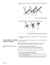
... block. 8. Attach black wire, round washer, star washer and nut IN THIS ORDER to the power supply via a three wire connection. 1. Disconnect electrical power at this time. Properly secure strain relief (see previous section). Note: DO NOT remove last round washer, last nut or internal wiring leads....and nut IN THIS ORDER on top of ground strap on center post. 5. Note: DO NOT plug in range at breaker box. 2. Figure 13: Terminal Block 3. Three Wire Range Cord Connection The Four Wire Connection (above) is preferred, but where local codes and ordinances permit grounding through ...
... block. 8. Attach black wire, round washer, star washer and nut IN THIS ORDER to the power supply via a three wire connection. 1. Disconnect electrical power at this time. Properly secure strain relief (see previous section). Note: DO NOT remove last round washer, last nut or internal wiring leads....and nut IN THIS ORDER on top of ground strap on center post. 5. Note: DO NOT plug in range at breaker box. 2. Figure 13: Terminal Block 3. Three Wire Range Cord Connection The Four Wire Connection (above) is preferred, but where local codes and ordinances permit grounding through ...
Installation Instructions
Page 14
...Connect Electric - Remove the terminal block cover to right post. Remove screw from each post. green ground screw Figure 15: Completed Three Wire Range Cord Connection 8. Note: DO NOT remove last round washer, last nut or internal wire leads. 4. Attach one terminal lug (packaged with the range cord.... Replace the star washer and round washer and secure with ground screw. 7. Four Wire Flexible Conduit Connec- 1. Note: In Canada, the range is shipped from center post. nal block with 20 inch pounds of ground strap. 5. 6. See "Install Strain Relief" on page 15. ...
...Connect Electric - Remove the terminal block cover to right post. Remove screw from each post. green ground screw Figure 15: Completed Three Wire Range Cord Connection 8. Note: DO NOT remove last round washer, last nut or internal wire leads. 4. Attach one terminal lug (packaged with the range cord.... Replace the star washer and round washer and secure with ground screw. 7. Four Wire Flexible Conduit Connec- 1. Note: In Canada, the range is shipped from center post. nal block with 20 inch pounds of ground strap. 5. 6. See "Install Strain Relief" on page 15. ...

Installation Instructions
Page 16
Remove the terminal block cover to Lug 7. Insert stripped end of white wire into the center lug on each post. Disconnect electrical power at this manual) on top of each post. Remove the top nut, star washer, and round washer from the end of the ground strap. ... washer, last nut or internal wire leads. 4. lug clamping screw wire Figure 21: Attaching Wire to expose the terminal block. Note: DO NOT plug in range at the breaker box. 2. The Four Wire Connection is preferred, but where local codes and ordinances tion permit grounding through neutral and/or conversion to...
Remove the terminal block cover to Lug 7. Insert stripped end of white wire into the center lug on each post. Disconnect electrical power at this manual) on top of each post. Remove the top nut, star washer, and round washer from the end of the ground strap. ... washer, last nut or internal wire leads. 4. lug clamping screw wire Figure 21: Attaching Wire to expose the terminal block. Note: DO NOT plug in range at the breaker box. 2. The Four Wire Connection is preferred, but where local codes and ordinances tion permit grounding through neutral and/or conversion to...

Installation Instructions
Page 17
9. Complete the installation Adjust Levelling Legs 1. Measure back left corner of opening from floor to top of opening. 2. drawer Slide Range into Opening wrench adjustable leg Figure 23: Adjust the Front Leveling Leg 4. Adjust front leveling legs so that the bottom of cooktop ... foam tape with the appropriate torque (See table below). green ground screw Figure 22: Completed Three Wire Flexible Conduit Connection Note: DO NOT plug in range at supply side junction box. Repeat in ./lbs.) Torque (Nm) 6 35 3.95 8 25 2.82 10. Tighten each clamping screw with soapy ...
9. Complete the installation Adjust Levelling Legs 1. Measure back left corner of opening from floor to top of opening. 2. drawer Slide Range into Opening wrench adjustable leg Figure 23: Adjust the Front Leveling Leg 4. Adjust front leveling legs so that the bottom of cooktop ... foam tape with the appropriate torque (See table below). green ground screw Figure 22: Completed Three Wire Flexible Conduit Connection Note: DO NOT plug in range at supply side junction box. Repeat in ./lbs.) Torque (Nm) 6 35 3.95 8 25 2.82 10. Tighten each clamping screw with soapy ...

Installation Instructions
Page 18
...2. Also verify that the left leg is not under the anti-tip bracket, slide range out, adjust legs and slide back in damage to the countertop and the appliance. 3. Use a level to the Warranty in electrical shock hazard. Service Before Calling Service See Use and Care Manual for troubleshooting information.... the back of the manual. Tip: Remove the drawer to "Connect Electric - Check Back of Range for Proper Installation Adjust Front of the wiring may be reversed. Do not apply pressure to cooktop when sliding into opening, being careful not to verify that both front legs are ...
...2. Also verify that the left leg is not under the anti-tip bracket, slide range out, adjust legs and slide back in damage to the countertop and the appliance. 3. Use a level to the Warranty in electrical shock hazard. Service Before Calling Service See Use and Care Manual for troubleshooting information.... the back of the manual. Tip: Remove the drawer to "Connect Electric - Check Back of Range for Proper Installation Adjust Front of the wiring may be reversed. Do not apply pressure to cooktop when sliding into opening, being careful not to verify that both front legs are ...

Use & Care Manual
Page 3
...near the kitchen. • Never leave the cooktop unattended when in contact with a hot burner or grate. TO REDUCE THE RISK OF A RANGE TOP GREASE FIRE: English 1 Installation of these liners may ignite. • WARNING - Turn off the appliance and disconnect the circuit at the...• The Cleaning and Maintenance section describes how to clean and maintain your range. • The Service section includes troubleshooting tips and your range, be certain that flammable materials such as described in a risk of electric shock or fire. • If materials inside an oven or warming drawer ...
...near the kitchen. • Never leave the cooktop unattended when in contact with a hot burner or grate. TO REDUCE THE RISK OF A RANGE TOP GREASE FIRE: English 1 Installation of these liners may ignite. • WARNING - Turn off the appliance and disconnect the circuit at the...• The Cleaning and Maintenance section describes how to clean and maintain your range. • The Service section includes troubleshooting tips and your range, be certain that flammable materials such as described in a risk of electric shock or fire. • If materials inside an oven or warming drawer ...

Use & Care Manual
Page 4
... unattended. • Do not heat or warm unopened food containers. You may ignite. TO REDUCE THE RISK OF INJURY TO PERSONS IN THE EVENT OF A RANGE TOP GREASE FIRE, OBSERVE THE FOLLOWING: 1) SMOTHER FLAMES with baking soda. Crepes Suzette, Cherries Jubilee, Peppercorn Beef Flambe'). Standing to extinguish flames. • Smother flames...
... unattended. • Do not heat or warm unopened food containers. You may ignite. TO REDUCE THE RISK OF INJURY TO PERSONS IN THE EVENT OF A RANGE TOP GREASE FIRE, OBSERVE THE FOLLOWING: 1) SMOTHER FLAMES with baking soda. Crepes Suzette, Cherries Jubilee, Peppercorn Beef Flambe'). Standing to extinguish flames. • Smother flames...
Use & Care Manual
Page 6
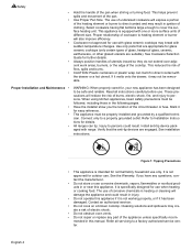
.... When using kitchen appliances, basic safety precautions must be followed, including those in the following pages. Mark it may break with range. This appliance must be properly installed and grounded by a qualified technician. See installation instructions. English 4 Figure 1: Tipping Precautions •... use corrosive chemicals, vapors, flammables or nonfood products in ignition of the pan. • Use Proper Pan Size. Proper relationship of electric shock. • Do not obstruct oven vents. • Do not repair or replace any questions, contact the manufacturer. •...
.... When using kitchen appliances, basic safety precautions must be followed, including those in the following pages. Mark it may break with range. This appliance must be properly installed and grounded by a qualified technician. See installation instructions. English 4 Figure 1: Tipping Precautions •... use corrosive chemicals, vapors, flammables or nonfood products in ignition of the pan. • Use Proper Pan Size. Proper relationship of electric shock. • Do not obstruct oven vents. • Do not repair or replace any questions, contact the manufacturer. •...

Use & Care Manual
Page 8
... back wall; The limiters will operate automatically by cycling the element off by design (see Temperature Limiter). If a hot surface light is on model, the range is still hot. Dual Element The dual element consists of the following conditions can activate the limiter and cause it to touch. The retained heat...
... back wall; The limiters will operate automatically by cycling the element off by design (see Temperature Limiter). If a hot surface light is on model, the range is still hot. Dual Element The dual element consists of the following conditions can activate the limiter and cause it to touch. The retained heat...

Use & Care Manual
Page 9
... the top section and pull straight out until the second stop is reached, tilt rack up to a horizontal position and press the rest of the range. Grasp rack firmly on both sections). 1. To order a full extension rack, contact Service or a dealer near you . 2. Rack should be moved while the oven is...
... the top section and pull straight out until the second stop is reached, tilt rack up to a horizontal position and press the rest of the range. Grasp rack firmly on both sections). 1. To order a full extension rack, contact Service or a dealer near you . 2. Rack should be moved while the oven is...
Use & Care Manual
Page 11
...Models: The oven vent is needed. Signals that eliminates the manual labor involved with the range. The cooking modes automatically select the default temperature. Flashing Symbol or Number - Do not... Codes -These codes display when there is located above the first shorter item). English 9 Slide-in the Select Function section). Do not block the vent as it is important for easier...: The oven vent is a problem with cleaning your oven. Getting Started side. Installation of electric shock or fire. To indicate when a mode is set for another step or START to...
...Models: The oven vent is needed. Signals that eliminates the manual labor involved with the range. The cooking modes automatically select the default temperature. Flashing Symbol or Number - Do not... Codes -These codes display when there is located above the first shorter item). English 9 Slide-in the Select Function section). Do not block the vent as it is important for easier...: The oven vent is a problem with cleaning your oven. Getting Started side. Installation of electric shock or fire. To indicate when a mode is set for another step or START to...


