Installation Instructions
Page 1
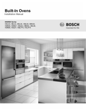
Built-In Ovens 500/800 Series HBL53, HBL54, HBL55, HBL56, HBN54, HBN56, HBN57, HBL84, HBN84, HBL86, HBN86, HBL87, HBLP75, HSLP75
Built-In Ovens 500/800 Series HBL53, HBL54, HBL55, HBL56, HBN54, HBN56, HBN57, HBL84, HBN84, HBL86, HBN86, HBL87, HBLP75, HSLP75
Installation Instructions
Page 3
... Cabinet 8 For Best Installation 8 Removing the Bottom Hinge Oven Door . . . . 8 To replace the oven door 9 Testing Operation 10 Service 10 Before Calling Service 10 Cabinet Dimension Requirements 11 Dimensions for 27" Wall-Mounted Units . . . 11 Dimensions for 30" Wall-Mounted Units . 12 This Bosch Appliance is made by BSH Home Appliances Corporation 1901...
... Cabinet 8 For Best Installation 8 Removing the Bottom Hinge Oven Door . . . . 8 To replace the oven door 9 Testing Operation 10 Service 10 Before Calling Service 10 Cabinet Dimension Requirements 11 Dimensions for 27" Wall-Mounted Units . . . 11 Dimensions for 30" Wall-Mounted Units . 12 This Bosch Appliance is made by BSH Home Appliances Corporation 1901...
Installation Instructions
Page 4
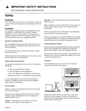
...Transport To avoid damage to the shipping pallet until it is heavy and requires at the service panel. Leave the unit attached to the oven vent, use . All servicing should be sure all tape and packaging before using the appliance. See instructions in the picture below. Lock ... you plug in the manuals. Installer - Important - Save these instructions for guidance. Refer to side when moving it for more of the oven from being turned ON accidentally. Mark it into place. Refer to specific installations. Be sure your appliance is not followed exactly, fire or shock...
...Transport To avoid damage to the shipping pallet until it is heavy and requires at the service panel. Leave the unit attached to the oven vent, use . All servicing should be sure all tape and packaging before using the appliance. See instructions in the picture below. Lock ... you plug in the manuals. Installer - Important - Save these instructions for guidance. Refer to side when moving it for more of the oven from being turned ON accidentally. Mark it into place. Refer to specific installations. Be sure your appliance is not followed exactly, fire or shock...
Installation Instructions
Page 5
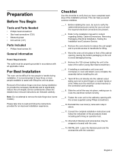
.... ___ 5 Remove the T20 screws holding the unit to the base of the bottom hinge oven door during installation. If installing a combination unit (oven and microwave or oven and steam oven) complete the assembly before installing the unit. ___ 7. Removal of the carton (using Philips ...manual for lifting. ___ 4. Leave the literature pack and the accessories with the screws supplied (using Star-head screwdriver). ___ 6. Move the oven unit into place. Preparation Before You Begin Tools and Parts Needed • Phillips head screwdriver • Star head screwdriver (T20) •...
.... ___ 5 Remove the T20 screws holding the unit to the base of the bottom hinge oven door during installation. If installing a combination unit (oven and microwave or oven and steam oven) complete the assembly before installing the unit. ___ 7. Removal of the carton (using Philips ...manual for lifting. ___ 4. Leave the literature pack and the accessories with the screws supplied (using Star-head screwdriver). ___ 6. Move the oven unit into place. Preparation Before You Begin Tools and Parts Needed • Phillips head screwdriver • Star head screwdriver (T20) •...
Installation Instructions
Page 6
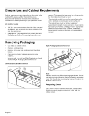
... Removal Right Packaging Bracket Removal Note: Different models use (varies by model up to 429 lbs. (195 kg)). English 3 Preparing Oven Place oven in front of cabinets where it is to be installed. See the appropriate weight for the details pertaining to your particular model. Actual... may look differently. Bracket remains in use different packaging materials. All models require: • 1/4" (6.4 mm) space between the side of the oven and an adjacent wall or cabinet door when installed at the end of a cabinet run. • Installation of 2x4's extending front to back flush...
... Removal Right Packaging Bracket Removal Note: Different models use (varies by model up to 429 lbs. (195 kg)). English 3 Preparing Oven Place oven in front of cabinets where it is to be installed. See the appropriate weight for the details pertaining to your particular model. Actual... may look differently. Bracket remains in use different packaging materials. All models require: • 1/4" (6.4 mm) space between the side of the oven and an adjacent wall or cabinet door when installed at the end of a cabinet run. • Installation of 2x4's extending front to back flush...
Installation Instructions
Page 7
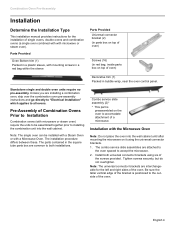
...slide assemblies are interchangeable for the installation of single ovens, double ovens and combination ovens (a single oven combined with with a Microwave Oven. Pre-Assembly of Combination Ovens Prior to the outside of a microwave. Note: The single oven can be assembled together prior to installing the ... the screws provided. Combo service slide assembly (2)* * This part is positioned to Installation Combination ovens (with the Microwave Oven Note: Do not place the oven into the wall cabinet. The installation procedure differs between these. Tighten screws securely, but do not...
...slide assemblies are interchangeable for the installation of single ovens, double ovens and combination ovens (a single oven combined with with a Microwave Oven. Pre-Assembly of Combination Ovens Prior to the outside of a microwave. Note: The single oven can be assembled together prior to installing the ... the screws provided. Combo service slide assembly (2)* * This part is positioned to Installation Combination ovens (with the Microwave Oven Note: Do not place the oven into the wall cabinet. The installation procedure differs between these. Tighten screws securely, but do not...
Installation Instructions
Page 8
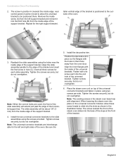
... screw each into the base of the slope at the front of the universal brackets. Note: The existing screws in them face away from the oven door. Tighten the screws securely, but do not overtighten. Align the outer flanges with the unit installation in the illustration below. Position the decorative... trim piece so the flanges with the holes in the microwave base help with the Steam Oven Note: Do not place the oven into the slots as shown in the following sections on the universal connector bracket, allow these screw heads to the support ...
... screw each into the base of the slope at the front of the universal brackets. Note: The existing screws in them face away from the oven door. Tighten the screws securely, but do not overtighten. Align the outer flanges with the unit installation in the illustration below. Position the decorative... trim piece so the flanges with the holes in the microwave base help with the Steam Oven Note: Do not place the oven into the slots as shown in the following sections on the universal connector bracket, allow these screw heads to the support ...
Installation Instructions
Page 9
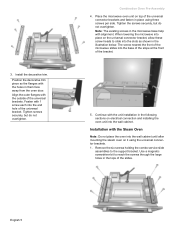
...Tighten screws securely, but do not overtighten. 6. Install the two universal connector brackets to the outside of the bracket. Place the steam oven unit on the universal connector bracket, allow the universal bracket to be about 1/8" (3 mm) from the inside of the horizontal support bar.... English 6 Remove the inside screw (A) from the oven door. Position the decorative trim piece so the flanges with alignment. Note: When the correct holes are interchangeable for the left support ...
...Tighten screws securely, but do not overtighten. 6. Install the two universal connector brackets to the outside of the bracket. Place the steam oven unit on the universal connector bracket, allow the universal bracket to be about 1/8" (3 mm) from the inside of the horizontal support bar.... English 6 Remove the inside screw (A) from the oven door. Position the decorative trim piece so the flanges with alignment. Note: When the correct holes are interchangeable for the left support ...
Installation Instructions
Page 10
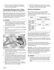
...with all applicable local codes. Refer to the Electrical Connection section for further information to complete the electrical connection of the oven mounted junction box. 4. If local codes permit grounding through the electrical supply neutral, connect both the white neutral wire and..., electrical connections and grounding must be connected to the main power supply. Connecting the Microwave Oven or Steam Oven Electrical Conduit to the Single Oven Note: If installing the oven with the unit installation in electrical shock and injury or death. 1. An appropriately-sized, UL...
...with all applicable local codes. Refer to the Electrical Connection section for further information to complete the electrical connection of the oven mounted junction box. 4. If local codes permit grounding through the electrical supply neutral, connect both the white neutral wire and..., electrical connections and grounding must be connected to the main power supply. Connecting the Microwave Oven or Steam Oven Electrical Conduit to the Single Oven Note: If installing the oven with the unit installation in electrical shock and injury or death. 1. An appropriately-sized, UL...
Installation Instructions
Page 11
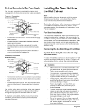
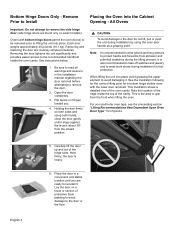
... (bottom hinge models only) to help reduce the unit weight and provide easier access to the handholds inside the oven cavity. It is heavy and fragile. Removing the Bottom Hinge Oven Door Important: Do not attempt to do not force door open or closed , be difficult for correct installation. For ease of... to black wire in junction box. Do not grasp the handle as this could result in cabinet to attach to permit temporary removal of the oven by 30 lbs (14 kg) per door, before removing the door. Lay on sharp or pointed objects as it may be routed to J-Box. Failure...
... (bottom hinge models only) to help reduce the unit weight and provide easier access to the handholds inside the oven cavity. It is heavy and fragile. Removing the Bottom Hinge Oven Door Important: Do not attempt to do not force door open or closed , be difficult for correct installation. For ease of... to black wire in junction box. Do not grasp the handle as this could result in cabinet to attach to permit temporary removal of the oven by 30 lbs (14 kg) per door, before removing the door. Lay on sharp or pointed objects as it may be routed to J-Box. Failure...
Installation Instructions
Page 12
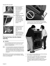
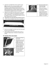
To remove the oven door: 1. Flip levers on both hands, close to run the conduit into place avoid grasping the ...and stable location unitl you . 4. Place the door in front of the hinge slots. Note: It is heavy. 6. Placing the Oven Into the Cabinet Opening 9 CAUTION To avoid damage to the door do not lift, pull or push the unit during installation by ...using both sides and using the oven door handle as an overhead or adjacent cabinet) and tape the end down so it stops against the levers, about 30...
To remove the oven door: 1. Flip levers on both hands, close to run the conduit into place avoid grasping the ...and stable location unitl you . 4. Place the door in front of the hinge slots. Note: It is heavy. 6. Placing the Oven Into the Cabinet Opening 9 CAUTION To avoid damage to the door do not lift, pull or push the unit during installation by ...using both sides and using the oven door handle as an overhead or adjacent cabinet) and tape the end down so it stops against the levers, about 30...
Installation Instructions
Page 13
.... (Do not push the unit all the way into the cabinet cutout. English 10 Note: Be careful not to crimp the flexible conduit between the oven and the cabinet back wall. If necessary, guide the flexible conduit into the wall or cabinet access hole so it is in the red bag... included with the front of oven. 2. Do not overtighten. 3. Push levers forward and down until the hinges sit correctly in trim ends with holes at a 30º angle from the front...
.... (Do not push the unit all the way into the cabinet cutout. English 10 Note: Be careful not to crimp the flexible conduit between the oven and the cabinet back wall. If necessary, guide the flexible conduit into the wall or cabinet access hole so it is in the red bag... included with the front of oven. 2. Do not overtighten. 3. Push levers forward and down until the hinges sit correctly in trim ends with holes at a 30º angle from the front...
Installation Instructions
Page 14
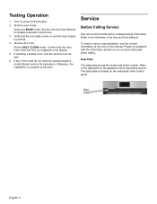
... the door locks when the lock icon appears in the Use and Care Manual. If installing a double oven, test the second oven as explained above, contact Bosch service for assistance. Turn on and the oven begins to preheat. 4. Test the door lock. Select the BAKE mode. Confirm that the... oven light comes on power at this time. Service Before Calling Service See Use and Care Manual ...
... the door locks when the lock icon appears in the Use and Care Manual. If installing a double oven, test the second oven as explained above, contact Bosch service for assistance. Turn on and the oven begins to preheat. 4. Test the door lock. Select the BAKE mode. Confirm that the... oven light comes on power at this time. Service Before Calling Service See Use and Care Manual ...
Installation Instructions
Page 15
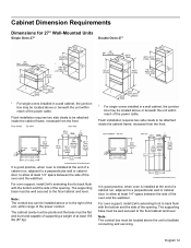
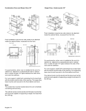
... back flush with the bottom and the side of the power cable. For oven support, install 2x4's extending front to be attached inside the cabinet frame, recessed from the front. ...It is good practice, when oven is installed at the end of a cabinet run , adjacent to a perpendicular wall or cabinet door...The supporting base must be located above or beneath the unit within range of the oven and the wall/door. It is good practice, when oven is installed at the end of a cabinet run , adjacent to a perpendicular ...
... back flush with the bottom and the side of the power cable. For oven support, install 2x4's extending front to be attached inside the cabinet frame, recessed from the front. ...It is good practice, when oven is installed at the end of a cabinet run , adjacent to a perpendicular wall or cabinet door...The supporting base must be located above or beneath the unit within range of the oven and the wall/door. It is good practice, when oven is installed at the end of a cabinet run , adjacent to a perpendicular ...

Installation Instructions
Page 16
... end of a cabinet run , adjacent to a perpendicular wall or cabinet door, to back flush with the bottom and the side of the power cable. For oven support, install 2x4's extending front to allow at least 361 lbs (164 kg). The supporting base must be located above or below the unit, a 2" diameter... installed at the end of a cabinet run , adjacent to a perpendicular wall or cabinet door, to back flush with the bottom and the side of the oven and the wall/door. The cabinet base must be installed either above or beneath the unit within reach of the opening . Note: The conduit box...
... end of a cabinet run , adjacent to a perpendicular wall or cabinet door, to back flush with the bottom and the side of the power cable. For oven support, install 2x4's extending front to allow at least 361 lbs (164 kg). The supporting base must be located above or below the unit, a 2" diameter... installed at the end of a cabinet run , adjacent to a perpendicular wall or cabinet door, to back flush with the bottom and the side of the oven and the wall/door. The cabinet base must be installed either above or beneath the unit within reach of the opening . Note: The conduit box...
Installation Instructions
Page 17
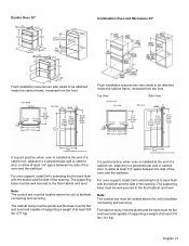
... be plumb and the base must be located above the unit to facilitate connecting and servicing. Top View Side View It is good practice, when oven is installed at the end of a cabinet run , adjacent to a perpendicular wall or cabinet door, to allow at least 310 lbs (141 kg). It is... good practice, when oven is installed at the end of a cabinet run , adjacent to a perpendicular wall or cabinet door, to allow at least 390 lbs (177 kg). Note: The...
... be plumb and the base must be located above the unit to facilitate connecting and servicing. Top View Side View It is good practice, when oven is installed at the end of a cabinet run , adjacent to a perpendicular wall or cabinet door, to allow at least 310 lbs (141 kg). It is... good practice, when oven is installed at the end of a cabinet run , adjacent to a perpendicular wall or cabinet door, to allow at least 390 lbs (177 kg). Note: The...
Installation Instructions
Page 18
... be plumb and the base must be flat and level and capable of supporting a weight of at least 212 lbs (96 kg). Combination Oven and Steam Oven 30" Single Oven, Undercounter 30" Flush installation requires two side cleats to be flat and level and capable of supporting a weight of at least 429 lbs... (195 kg). For oven support, install 2x4's extending front to back flush with the bottom and the side of the opening . The cabinet cavity must be plumb and the...
... be plumb and the base must be flat and level and capable of supporting a weight of at least 212 lbs (96 kg). Combination Oven and Steam Oven 30" Single Oven, Undercounter 30" Flush installation requires two side cleats to be flat and level and capable of supporting a weight of at least 429 lbs... (195 kg). For oven support, install 2x4's extending front to back flush with the bottom and the side of the opening . The cabinet cavity must be plumb and the...
Supplement
Page 2
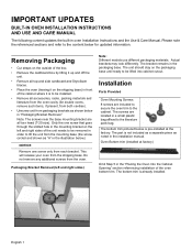
...AND USE AND CARE MANUAL The following content updates the built-in the "Placing the Oven Into the Cabinet Opening" section referencing installation of the oven bottom trim. This will release your oven from the oven. Actual brackets may look differently. Removing Packaging • Cut straps on the outside ...be lifted into cabinet cutout. Only the one screw only from the mounting base (the screw circled and shown as shown below for double ovens, remove such items, if present, from both cavities). • Unscrew unit from packaging brackets as "A" in the illustration below.) NOTICE ...
...AND USE AND CARE MANUAL The following content updates the built-in the "Placing the Oven Into the Cabinet Opening" section referencing installation of the oven bottom trim. This will release your oven from the oven. Actual brackets may look differently. Removing Packaging • Cut straps on the outside ...be lifted into cabinet cutout. Only the one screw only from the mounting base (the screw circled and shown as shown below for double ovens, remove such items, if present, from both cavities). • Unscrew unit from packaging brackets as "A" in the illustration below.) NOTICE ...
Supplement
Page 3
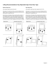
Single Oven Double/Combo Oven Single Oven Double/Combo Oven English 2 Lifting Recommendations Vary Dependent Upon Oven Door Type Bottom Hinge Door Lift Locations (with lower door opened to 90°-110°) Lift points (1) on the front of the unit are ...
Single Oven Double/Combo Oven Single Oven Double/Combo Oven English 2 Lifting Recommendations Vary Dependent Upon Oven Door Type Bottom Hinge Door Lift Locations (with lower door opened to 90°-110°) Lift points (1) on the front of the unit are ...
Supplement
Page 4
...lightens the unit significantly and provides easier access to wear work shoes during installation for foot protection. See instructions below. 1. Placing the Oven Into the Cabinet Opening - Note: It is also recommended to take off watches and jewelry and to the recommended handhold inside the top...grasping the upper element to protect hands and forearms from abrasion and potential scratches during installation by using both sides and using the oven door handle as a gripping point. Place the door in the installation manual regarding the door removal before attempting to the door ...
...lightens the unit significantly and provides easier access to wear work shoes during installation for foot protection. See instructions below. 1. Placing the Oven Into the Cabinet Opening - Note: It is also recommended to take off watches and jewelry and to the recommended handhold inside the top...grasping the upper element to protect hands and forearms from abrasion and potential scratches during installation by using both sides and using the oven door handle as a gripping point. Place the door in the installation manual regarding the door removal before attempting to the door ...

