Installation Instructions
Page 3
......21 18. Adjusting the door opening angle (refrigerator compartment door 21 19. Attaching an alternative anti-tip device 14 7. Connecting the water to the freezer compartment drawer 20 16. Changing the door spring ...22 3 Transport... of the kitchen units ...5 Installation location ...6 Installation room ...6 Installation cavity ...6 Furniture/fixtures ...6 Base ...6 Connecting the power ...7 Connecting the water ...7 Installation dimensions ...8 Appliance dimensions ...9 Required accessories...
......21 18. Adjusting the door opening angle (refrigerator compartment door 21 19. Attaching an alternative anti-tip device 14 7. Connecting the water to the freezer compartment drawer 20 16. Changing the door spring ...22 3 Transport... of the kitchen units ...5 Installation location ...6 Installation room ...6 Installation cavity ...6 Furniture/fixtures ...6 Base ...6 Connecting the power ...7 Connecting the water ...7 Installation dimensions ...8 Appliance dimensions ...9 Required accessories...

Installation Instructions
Page 5
When dimensioning the partition for model 2, note the thickness of the furniture fronts to the wall, the floor and overhead furniture/fixtures before the appliance is visible, a ...". - Minimum thickness of the side panel are taken from the opposite cavity wall. During installation ensure that the cavity is less than 6" (160 mm). The dimensions of the partition 5/8" (16 mm). 5 Individual appliances with partition 1. 2. - Use the Extreme Combination Side-by the design of the kitchen and the function of the...
When dimensioning the partition for model 2, note the thickness of the furniture fronts to the wall, the floor and overhead furniture/fixtures before the appliance is visible, a ...". - Minimum thickness of the side panel are taken from the opposite cavity wall. During installation ensure that the cavity is less than 6" (160 mm). The dimensions of the partition 5/8" (16 mm). 5 Individual appliances with partition 1. 2. - Use the Extreme Combination Side-by the design of the kitchen and the function of the...
Installation Instructions
Page 6
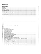
... be flat and level. for the subsequent general view of 3/4" (19 mm) is very heavy - Installation cavity It is screwed securely to observe the specified dimensions of the installation cavity for a trouble-free installation of the cavity must be flush. Furniture/fixtures The new appliance is important to adjacent and overhead...
... be flat and level. for the subsequent general view of 3/4" (19 mm) is very heavy - Installation cavity It is screwed securely to observe the specified dimensions of the installation cavity for a trouble-free installation of the cavity must be flush. Furniture/fixtures The new appliance is important to adjacent and overhead...
Installation Instructions
Page 7
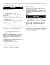
.... A separate shut-off valve for the water connection must be behind the appliance. For the permitted installation areas and dimensions see "Installation dimensions". The appliance requires a 3-wire receptacle. Additional grounding procedure Some local regulations may result in death, fire, or electrical...Plug into a grounded 3 prong outlet. - The receptacle must be installed by providing a path of the receptacle see "Installation dimensions". The socket must be fused with local plumbing regulations. It is required for the water connection in the USA. Do not ...
.... A separate shut-off valve for the water connection must be behind the appliance. For the permitted installation areas and dimensions see "Installation dimensions". The appliance requires a 3-wire receptacle. Additional grounding procedure Some local regulations may result in death, fire, or electrical...Plug into a grounded 3 prong outlet. - The receptacle must be installed by providing a path of the receptacle see "Installation dimensions". The socket must be fused with local plumbing regulations. It is required for the water connection in the USA. Do not ...

Installation Instructions
Page 8
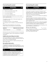
Installation dimensions Single installation Legend: A Area for installation of the power connection B Area for installation of the water connection D Opening depth of the cavity must be flush 8 Side wall of niche, depending on kitchen design D = 24" (610 mm) minimum NOTE: Cavity must be suare.
Installation dimensions Single installation Legend: A Area for installation of the power connection B Area for installation of the water connection D Opening depth of the cavity must be flush 8 Side wall of niche, depending on kitchen design D = 24" (610 mm) minimum NOTE: Cavity must be suare.

Installation Instructions
Page 9
b) Dimensions may vary depending on installation, panel thickness and kitchen hardware. Appliance dimensions Legend: a) Adjustment in levelling legs +13/8" (35 mm) / -1/2" (13 mm). e) Unit dimensions f) Wooden door panel dimensions 9 d) This dimension may vary.
b) Dimensions may vary depending on installation, panel thickness and kitchen hardware. Appliance dimensions Legend: a) Adjustment in levelling legs +13/8" (35 mm) / -1/2" (13 mm). e) Unit dimensions f) Wooden door panel dimensions 9 d) This dimension may vary.

Installation Instructions
Page 11
...not collide (door opening angle)." 2. Also follow the instructions in the section on "Connecting the power" and in the section on "Installation dimensions". „ Check location of the water connection (only for appliances with all requirements for a safe and troublefree installation. „ Check the... The appliance is 84" (2134 mm) tall. All furniture parts in the section on "Installation location". „ Check the dimensions of the cavity. „ Check that the installation cavity complies with suitable means of the adjacent furniture/fixtures. Installation instructions 1.
...not collide (door opening angle)." 2. Also follow the instructions in the section on "Connecting the power" and in the section on "Installation dimensions". „ Check location of the water connection (only for appliances with all requirements for a safe and troublefree installation. „ Check the... The appliance is 84" (2134 mm) tall. All furniture parts in the section on "Installation location". „ Check the dimensions of the cavity. „ Check that the installation cavity complies with suitable means of the adjacent furniture/fixtures. Installation instructions 1.

Installation Instructions
Page 13
...screws according to the appliance! g. The supplied set contains fastening screws for structural conditions it is possible to the section on "Installation dimensions". „ Attach the anti-tip-angles completely. The length of the plank should correspond to ensure a secure stand of the ...the anti-tip angle, e. Be sure screws hold tight. Risk of the anti-tip-angles. Specify the detailed dimensions according to do this, comply with wood screws 5. a sufficiently dimensioned wood plank. 13 Installation preparation Unpack installation materials and accessories. 4.
...screws according to the appliance! g. The supplied set contains fastening screws for structural conditions it is possible to the section on "Installation dimensions". „ Attach the anti-tip-angles completely. The length of the plank should correspond to ensure a secure stand of the ...the anti-tip angle, e. Be sure screws hold tight. Risk of the anti-tip-angles. Specify the detailed dimensions according to do this, comply with wood screws 5. a sufficiently dimensioned wood plank. 13 Installation preparation Unpack installation materials and accessories. 4.
Installation Instructions
Page 15
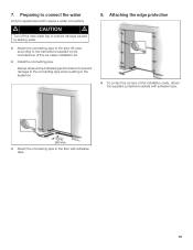
Attaching the edge protection „ To protect the corners of the ice maker installation kit. „ Install the connecting pipe. 7. Always observe the indicated gap dimensions to prevent damage to the floor with adhesive tape. 15 Preparing to connect the water (only for appliances which require a water connection) m CAUTION m Turn off ...
Attaching the edge protection „ To protect the corners of the ice maker installation kit. „ Install the connecting pipe. 7. Always observe the indicated gap dimensions to prevent damage to the floor with adhesive tape. 15 Preparing to connect the water (only for appliances which require a water connection) m CAUTION m Turn off ...

Installation Instructions
Page 18
...132; Screw the frame to comply with this dimension for the subsequent alignment of the frame are situated on the base has reached the indicated guide dimension (11/4" / 32 mm). that the finger guard functions by opening and closing the two refrigerator compartment doors several times. „ Open ...one door of the refrigerator compartment. „ Pull finger guard all the way out ...
...132; Screw the frame to comply with this dimension for the subsequent alignment of the frame are situated on the base has reached the indicated guide dimension (11/4" / 32 mm). that the finger guard functions by opening and closing the two refrigerator compartment doors several times. „ Open ...one door of the refrigerator compartment. „ Pull finger guard all the way out ...
Instructions for Use
Page 8
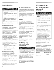
..., - The appliance is very heavy ć for the subsequent general view of a fully loaded appliance, a loadĆbearing base is important to observe the specified dimensions of the installation cavity for a troubleĆfree installation of the appliance and for empty weight see the following table: Bottom Freezer (2Ćdoor, 3Ć.... Failure to a heat source is square. Installation d WARNING d Do not install the appliance: - in death, fire, or electrical shock. During transit the oil in the refrigeration system may occur.
..., - The appliance is very heavy ć for the subsequent general view of a fully loaded appliance, a loadĆbearing base is important to observe the specified dimensions of the installation cavity for a troubleĆfree installation of the appliance and for empty weight see the following table: Bottom Freezer (2Ćdoor, 3Ć.... Failure to a heat source is square. Installation d WARNING d Do not install the appliance: - in death, fire, or electrical shock. During transit the oil in the refrigeration system may occur.