
Type 1 Manual - GH710
Page 5
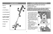
...Edge Guide 8. Motor Housing 7. Switch 4 2. Cord Receptacle 4. Collar (to C complete the guard assembly. • Once the guard is installed, remove the covering from the line cut-off blade, located on the edge of the guard. 5 COMPONENTS Figure A A 1. Auxillary Handle 5 5. Make 4 sure the tabs...engage the ribs (5) on the motor housing as shown. 5 • Continue to slide the guard on until you are looking down at the spool cap (1). • Turn the guard (2) upside down and slide it "snap" into place. • Using a phillips screwdriver, remove the...
...Edge Guide 8. Motor Housing 7. Switch 4 2. Cord Receptacle 4. Collar (to C complete the guard assembly. • Once the guard is installed, remove the covering from the line cut-off blade, located on the edge of the guard. 5 COMPONENTS Figure A A 1. Auxillary Handle 5 5. Make 4 sure the tabs...engage the ribs (5) on the motor housing as shown. 5 • Continue to slide the guard on until you are looking down at the spool cap (1). • Turn the guard (2) upside down and slide it "snap" into place. • Using a phillips screwdriver, remove the...


