

Setup Manual
Page 1
... part or in whole, is subject to be responsible for any party beforehand. Duplication of this user's manual. MCP6PB M2+/N68S Setup Manual FCC Information and Copyright This equipment has been tested and found in this user's manual is not allowed without notice and we will not occur in a residential installation. These limits are...
... part or in whole, is subject to be responsible for any party beforehand. Duplication of this user's manual. MCP6PB M2+/N68S Setup Manual FCC Information and Copyright This equipment has been tested and found in this user's manual is not allowed without notice and we will not occur in a residential installation. These limits are...

Setup Manual
Page 3
...disconnect the computer from power outlet before operation. „ Before you for ATX Case X 1 Installation Guide X 1 Fully Setup Driver CD X 1 (full version manual files inside) FDD Cable X 1 (optional) USB 2.0 Cable X1 (optional) Serial ATA Power Cable X 1 (optional) Note: The package contents may damage ...132; Keep the computer from anti-static bag, ground yourself properly by area or your motherboard version. 1 CHAPTER 1: INTRODUCTION MCP6PB M2+/N68S 1.1 BEFORE YOU START Thank you take the motherboard out from dangerous area, such as heat source, humid air and water. 1.2 PACKAGE ...
...disconnect the computer from power outlet before operation. „ Before you for ATX Case X 1 Installation Guide X 1 Fully Setup Driver CD X 1 (full version manual files inside) FDD Cable X 1 (optional) USB 2.0 Cable X1 (optional) Serial ATA Power Cable X 1 (optional) Note: The package contents may damage ...132; Keep the computer from anti-static bag, ground yourself properly by area or your motherboard version. 1 CHAPTER 1: INTRODUCTION MCP6PB M2+/N68S 1.1 BEFORE YOU START Thank you take the motherboard out from dangerous area, such as heat source, humid air and water. 1.2 PACKAGE ...

Setup Manual
Page 4
Motherboard Manual 1.3 MOTHERBOARD FEATURES SPEC Socket AM2+ AMD 64 Architecture enables 32 and 64 bit ... Ghz FSB Supports up to 2 GT/s Bandwidth Chipset GeForce 6150 SE/nForce 430 (MCP6P M2+) GeForce 7025/nForce 630a (N68S) ITE 8718F Super I/O Provides the most commonly used legacy Super I/O functionality Low Pin Count Interface Environment Control initiatives H/W Monitor... DIMM and ECC DIMM is not supported Graphics GeForce 6150 SE/nForce 430 (MCP6P M2+) GeForce 7025/nForce 630a (N68S) Max Shared Video Memory is 256MB IDE Integrated IDE Controller Ultra DMA 33 / 66 / 100 / 133 Bus...
Motherboard Manual 1.3 MOTHERBOARD FEATURES SPEC Socket AM2+ AMD 64 Architecture enables 32 and 64 bit ... Ghz FSB Supports up to 2 GT/s Bandwidth Chipset GeForce 6150 SE/nForce 430 (MCP6P M2+) GeForce 7025/nForce 630a (N68S) ITE 8718F Super I/O Provides the most commonly used legacy Super I/O functionality Low Pin Count Interface Environment Control initiatives H/W Monitor... DIMM and ECC DIMM is not supported Graphics GeForce 6150 SE/nForce 430 (MCP6P M2+) GeForce 7025/nForce 630a (N68S) Max Shared Video Memory is 256MB IDE Integrated IDE Controller Ultra DMA 33 / 66 / 100 / 133 Bus...

Setup Manual
Page 8
Motherboard Manual Step 4: Hold the CPU down firmly, and then close the lever toward direct B to boot while using AM2+ CPUs. This completes the installation. Due to ...
Motherboard Manual Step 4: Hold the CPU down firmly, and then close the lever toward direct B to boot while using AM2+ CPUs. This completes the installation. Due to ...
Setup Manual
Page 10
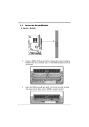
Insert the DIMM vertically and firmly into the slot until the retaining chip snap back in place and the DIMM is properly seated. 8 Align a DIMM on the slot so that the notch on the DIMM matches the break on the Slot. 2. DIM MA1 DIM MB1 Motherboard Manual 2.3 INSTALLING SYSTEM MEMORY A. Memory Modules 1. Unlock a DIMM slot by pressing the retaining clips outward.
Insert the DIMM vertically and firmly into the slot until the retaining chip snap back in place and the DIMM is properly seated. 8 Align a DIMM on the slot so that the notch on the DIMM matches the break on the Slot. 2. DIM MA1 DIM MB1 Motherboard Manual 2.3 INSTALLING SYSTEM MEMORY A. Memory Modules 1. Unlock a DIMM slot by pressing the retaining clips outward.
Setup Manual
Page 12
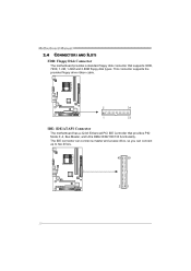
Motherboard Manual 2.4 CONNECTORS AND SLOTS FDD: Floppy Disk Connector The motherboard provides a standard floppy disk connector that provides PIO Mode 0~4, Bus Master, and Ultra DMA 33/66/100/133 functionality. The IDE connector can connect a master and a slave drive, so you can connect up to two drives. 40 39 21 10 This connector supports the provided floppy drive ribbon cable. 2 34 1 33 IDE: IDE/ATAPI Connector The motherboard has a 32-bit Enhanced PCI IDE Controller that supports 360K, 720K, 1.2M, 1.44M and 2.88M floppy disk types.
Motherboard Manual 2.4 CONNECTORS AND SLOTS FDD: Floppy Disk Connector The motherboard provides a standard floppy disk connector that provides PIO Mode 0~4, Bus Master, and Ultra DMA 33/66/100/133 functionality. The IDE connector can connect a master and a slave drive, so you can connect up to two drives. 40 39 21 10 This connector supports the provided floppy drive ribbon cable. 2 34 1 33 IDE: IDE/ATAPI Connector The motherboard has a 32-bit Enhanced PCI IDE Controller that supports 360K, 720K, 1.2M, 1.44M and 2.88M floppy disk types.

Setup Manual
Page 14
... 13 LED 14 Reset button 15 16 Assignment N/A N/A N/A Power LED (+) Power LED (+) Power LED (-) Power button Ground Function N/A N/A Power LED Power-on button 12 Motherboard Manual CHAPTER 3: HEADERS & JUMPERS SETUP 3.1 HOW TO SETUP JUMPERS The illustration shows how to connect the PC case's front panel switch functions.
... 13 LED 14 Reset button 15 16 Assignment N/A N/A N/A Power LED (+) Power LED (+) Power LED (-) Power button Ground Function N/A N/A Power LED Power-on button 12 Motherboard Manual CHAPTER 3: HEADERS & JUMPERS SETUP 3.1 HOW TO SETUP JUMPERS The illustration shows how to connect the PC case's front panel switch functions.

Setup Manual
Page 16
Motherboard Manual JUSB2/JUSB3: Headers for USB 2.0 Ports at Front Panel These headers allow user to SATA Controller with 2 channels SATA interface, it satisfies the SATA 2.0 spec ...
Motherboard Manual JUSB2/JUSB3: Headers for USB 2.0 Ports at Front Panel These headers allow user to SATA Controller with 2 channels SATA interface, it satisfies the SATA 2.0 spec ...

Setup Manual
Page 18
Wait for five seconds. 4. Motherboard Manual JCMOS1: Clear CMOS Header By placing the jumper on the AC. 6. Remove AC power line. 2. Reset your desired password or clear the CMOS data. 16 Power on pin2-3, it allows user to restore the BIOS safe setting and the CMOS data, please carefully follow the procedures to avoid damaging the motherboard. 31 Pin 1-2 Close: Normal Operation (default). 31 31 Pin 2-3 Close: Clear CMOS data. ※ Clear CMOS Procedures: 1. Set the jumper to "Pin 2-3 close ". 5. Set the jumper to "Pin 1-2 close ". 3.
Wait for five seconds. 4. Motherboard Manual JCMOS1: Clear CMOS Header By placing the jumper on the AC. 6. Remove AC power line. 2. Reset your desired password or clear the CMOS data. 16 Power on pin2-3, it allows user to restore the BIOS safe setting and the CMOS data, please carefully follow the procedures to avoid damaging the motherboard. 31 Pin 1-2 Close: Normal Operation (default). 31 31 Pin 2-3 Close: Clear CMOS data. ※ Clear CMOS Procedures: 1. Set the jumper to "Pin 2-3 close ". 5. Set the jumper to "Pin 1-2 close ". 3.
Setup Manual
Page 20
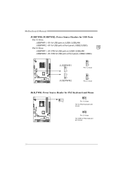
JUSBPWR2: +5V STB for USB ports at JUSB1/JUSBLAN1. Motherboard Manual JUSBPWR1/JUSBPWR2: Power Source Headers for USB Ports Pin 1-2 Close: JUSBPWR1: +5V for USB ports at front panel (JUSB2/JUSB3). JUSBPWR1 1 3 3 1 JUSBPWR2 1 3 Pin 1-2 close 1 3 Pin 2-3 close JKB_PWR: Power Source Header for PS/2 Keyboard and Mouse 1 3 1 3 Pin 1-2 close +5V for PS/2 keyboard and mouse. 1 3 Pin 2-3 close +5V STB for USB ports at front panel (JUSB2/JUSB3). Pin 2-3 Close: JUSBPWR1: +5V STB for PS/2 keyboard and mouse. 18 JUSBPWR2: +5V for USB ports at JUSB1/JUSBLAN1.
JUSBPWR2: +5V STB for USB ports at JUSB1/JUSBLAN1. Motherboard Manual JUSBPWR1/JUSBPWR2: Power Source Headers for USB Ports Pin 1-2 Close: JUSBPWR1: +5V for USB ports at front panel (JUSB2/JUSB3). JUSBPWR1 1 3 3 1 JUSBPWR2 1 3 Pin 1-2 close 1 3 Pin 2-3 close JKB_PWR: Power Source Header for PS/2 Keyboard and Mouse 1 3 1 3 Pin 1-2 close +5V for PS/2 keyboard and mouse. 1 3 Pin 2-3 close +5V STB for USB ports at front panel (JUSB2/JUSB3). Pin 2-3 Close: JUSBPWR1: +5V STB for PS/2 keyboard and mouse. 18 JUSBPWR2: +5V for USB ports at JUSB1/JUSBLAN1.
Setup Manual
Page 22
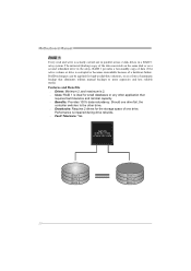
... (backup) copy of the data can be applied for high-availability solutions, or as a form of automatic backup that eliminates tedious manual backups to the other drive. Drawbacks: Requires 2 drives for small databases or any other application that requires fault tolerance and... minimal capacity. Benefits: Provides 100% data redundancy. Block 1 Block 2 Block 3 20 Block 1 Block 2 Block 3 Motherboard Manual RAID 1: Every read and write is impaired during drive rebuilds. Fault Tolerance: Yes. Should one drive. RAID 1 provides a hot-standby copy...
... (backup) copy of the data can be applied for high-availability solutions, or as a form of automatic backup that eliminates tedious manual backups to the other drive. Drawbacks: Requires 2 drives for small databases or any other application that requires fault tolerance and... minimal capacity. Benefits: Provides 100% data redundancy. Block 1 Block 2 Block 3 20 Block 1 Block 2 Block 3 Motherboard Manual RAID 1: Every read and write is impaired during drive rebuilds. Fault Tolerance: Yes. Should one drive. RAID 1 provides a hot-standby copy...
Setup Manual
Page 23
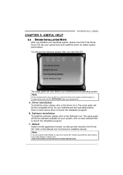
...installation program. C. Please download the latest version of Acrobat Reader software from the paperback manual, we also provide manual in the Driver CD. CHAPTER 5: USEFUL HELP MCP6PB M2+/N68S 5.1 DRIVER INSTALLATION NOTE After you installed your operating system, please insert the Fully ...Setup Driver CD into your optical drive and install the driver for your motherboard and operating system. A. Manual Aside from http://www.adobe.com ...
...installation program. C. Please download the latest version of Acrobat Reader software from the paperback manual, we also provide manual in the Driver CD. CHAPTER 5: USEFUL HELP MCP6PB M2+/N68S 5.1 DRIVER INSTALLATION NOTE After you installed your operating system, please insert the Fully ...Setup Driver CD into your optical drive and install the driver for your motherboard and operating system. A. Manual Aside from http://www.adobe.com ...

Setup Manual
Page 24
... update boo logo: 1. BIOScreen Utility This utility allows you to customize your boot logo easily. Please follow the following instructions to complete the installation. Motherboard Manual 5.2 SOFTWARE Installing Software 1. Transform:Transform the picture for BIOS and preview the result. 3. Insert the Setup CD to complete the update. 22 You can...
... update boo logo: 1. BIOScreen Utility This utility allows you to customize your boot logo easily. Please follow the following instructions to complete the installation. Motherboard Manual 5.2 SOFTWARE Installing Software 1. Transform:Transform the picture for BIOS and preview the result. 3. Insert the Setup CD to complete the update. 22 You can...

Setup Manual
Page 26
... support. 2. check the drive type in the system. 1. drive. work 3. Screen message shows "Invalid Configuration" or "CMOS Failure." System only boots from a hard disk 1. Motherboard Manual 5.5 TROUBLESHOOTING Probable Solution 1. System cannot boot after user installs a 1.
... support. 2. check the drive type in the system. 1. drive. work 3. Screen message shows "Invalid Configuration" or "CMOS Failure." System only boots from a hard disk 1. Motherboard Manual 5.5 TROUBLESHOOTING Probable Solution 1. System cannot boot after user installs a 1.

