Setup Manual
Page 1
The content of this user's manual is subject to be responsible for any mistakes found to comply with the instructions, may cause harmful interference to Part 15 of the FCC Rules. ..., is no representations or warranties with respect to provide reasonable protection against harmful interference in a residential installation. MCP6P3/N68S3 Setup Manual FCC Information and Copyright This equipment has been tested and found in this user's manual. Duplication of a Class B digital device, pursuant to radio communications. All the brand and product names are designed...
The content of this user's manual is subject to be responsible for any mistakes found to comply with the instructions, may cause harmful interference to Part 15 of the FCC Rules. ..., is no representations or warranties with respect to provide reasonable protection against harmful interference in a residential installation. MCP6P3/N68S3 Setup Manual FCC Information and Copyright This equipment has been tested and found in this user's manual. Duplication of a Class B digital device, pursuant to radio communications. All the brand and product names are designed...
Setup Manual
Page 3
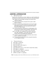
...equipment. Do not leave any safely grounded appliance, or use grounded wrist strap to area or your motherboard version. 1 CHAPTER 1: INTRODUCTION MCP6P3/N68S3 1.1 BEFORE YOU START Thank you follow the instructions below: Prepare a dry and stable working environment with sufficient lighting. Keep the...start installing the motherboard, please make sure you for ATX Case X 1 Installation Guide X 1 Fully Setup Driver CD X 1 (full version manual files inside the case after installation. Loose parts will cause short circuits which may be 0 to bend or flex the board. Avoid touching the...
...equipment. Do not leave any safely grounded appliance, or use grounded wrist strap to area or your motherboard version. 1 CHAPTER 1: INTRODUCTION MCP6P3/N68S3 1.1 BEFORE YOU START Thank you follow the instructions below: Prepare a dry and stable working environment with sufficient lighting. Keep the...start installing the motherboard, please make sure you for ATX Case X 1 Installation Guide X 1 Fully Setup Driver CD X 1 (full version manual files inside the case after installation. Loose parts will cause short circuits which may be 0 to bend or flex the board. Avoid touching the...
Setup Manual
Page 4
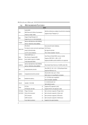
... Each connector supports 1 SATA device Front Panel Connector x1 Supports front panel facilities 2 SATA Version 2.0 specification compliant. Motherboard Manual 1.3 MOTHERBOARD FEATURES SPEC Socket AM3 AMD 64 Architecture enables 32 and 64 bit computing CPU AMD Phenom II/ Athlon II ... Transport 2.0 (Maximum Watt: 95W) Support HyperTransport 2.0 FSB Supports up to 2.0 GT/s Bandwidth Chipset GeForce 6150 SE/nForce 430 (MCP6P3) GeForce 7025/nForce 630a (N68S3) ITE 8718F Environment Control initiatives, Provides the most commonly used legacy H/W Monitor Super I/O Super I/O...
... Each connector supports 1 SATA device Front Panel Connector x1 Supports front panel facilities 2 SATA Version 2.0 specification compliant. Motherboard Manual 1.3 MOTHERBOARD FEATURES SPEC Socket AM3 AMD 64 Architecture enables 32 and 64 bit computing CPU AMD Phenom II/ Athlon II ... Transport 2.0 (Maximum Watt: 95W) Support HyperTransport 2.0 FSB Supports up to 2.0 GT/s Bandwidth Chipset GeForce 6150 SE/nForce 430 (MCP6P3) GeForce 7025/nForce 630a (N68S3) ITE 8718F Environment Control initiatives, Provides the most commonly used legacy H/W Monitor Super I/O Super I/O...

Setup Manual
Page 6
Motherboard Manual 1.5 MOTHERBOARD LAYOUT KBMS1 AT X P W R2 JK B _P WR CP U_FAN1 COM1 DDR3_A1 DDR3_B1 Socket AM3 VGA1 USB1 RJ45USB1 JUS B V 1 AT X P WR1 AUDIO1 F _ A UDIO 1 -"/ BAT1 GeForce 6150 SE/7025 nForce 430/630a PEX16_1 PCI1 Codec JP RINT 1 PCI2 FDD1 JS P DIF O UT 1 Note: ■ represents the 1st pin. Super I/O JUS B V2 IDE1 F_USB2 F_USB1 BIOS JCMOS1 SATA2 SATA4 SATA1 SATA3 S YS_FAN1 PANEL1 4
Motherboard Manual 1.5 MOTHERBOARD LAYOUT KBMS1 AT X P W R2 JK B _P WR CP U_FAN1 COM1 DDR3_A1 DDR3_B1 Socket AM3 VGA1 USB1 RJ45USB1 JUS B V 1 AT X P WR1 AUDIO1 F _ A UDIO 1 -"/ BAT1 GeForce 6150 SE/7025 nForce 430/630a PEX16_1 PCI1 Codec JP RINT 1 PCI2 FDD1 JS P DIF O UT 1 Note: ■ represents the 1st pin. Super I/O JUS B V2 IDE1 F_USB2 F_USB1 BIOS JCMOS1 SATA2 SATA4 SATA1 SATA3 S YS_FAN1 PANEL1 4

Setup Manual
Page 8
Connect the CPU FAN power cable to complete the installation. This completes the installation. 6 Step 4: Put the CPU Fan on the CPU and buckle it. Motherboard Manual Step 3: Hold the CPU down firmly, and then close the lever toward direct B to the CPU_FAN1.
Connect the CPU FAN power cable to complete the installation. This completes the installation. 6 Step 4: Put the CPU Fan on the CPU and buckle it. Motherboard Manual Step 3: Hold the CPU down firmly, and then close the lever toward direct B to the CPU_FAN1.

Setup Manual
Page 10
Align a DIMM on the slot such that the notch on the DIMM matches the break on the Slot. 2. Memory Modules 1. Insert the DIMM vertically and firmly into the slot until the retaining chip snap back in place and the DIMM is properly seated. 8 D D R3 _A 1 D D R3 _B 1 Motherboard Manual 2.3 INSTALLING SYSTEM MEMORY A. Unlock a DIMM slot by pressing the retaining clips outward.
Align a DIMM on the slot such that the notch on the DIMM matches the break on the Slot. 2. Memory Modules 1. Insert the DIMM vertically and firmly into the slot until the retaining chip snap back in place and the DIMM is properly seated. 8 D D R3 _A 1 D D R3 _B 1 Motherboard Manual 2.3 INSTALLING SYSTEM MEMORY A. Unlock a DIMM slot by pressing the retaining clips outward.
Setup Manual
Page 12
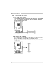
Motherboard Manual 2.4 CONNECTORS AND SLOTS FDD1: Floppy Disk Connector The motherboard provides a standard floppy disk connector that provides PIO Mode 0~4, Bus Master, and Ultra DMA 33/66/100/133 functionality. The IDE connector can connect a master and a slave drive, so you can connect up to two drives. 40 39 2 1 10 This connector supports the provided floppy drive ribbon cables. 2 34 1 33 IDE1: IDE/ATAPI Connector The motherboard has a 32-bit Enhanced PCI IDE Controller that supports 360K, 720K, 1.2M, 1.44M and 2.88M floppy disk types.
Motherboard Manual 2.4 CONNECTORS AND SLOTS FDD1: Floppy Disk Connector The motherboard provides a standard floppy disk connector that provides PIO Mode 0~4, Bus Master, and Ultra DMA 33/66/100/133 functionality. The IDE connector can connect a master and a slave drive, so you can connect up to two drives. 40 39 2 1 10 This connector supports the provided floppy drive ribbon cables. 2 34 1 33 IDE1: IDE/ATAPI Connector The motherboard has a 32-bit Enhanced PCI IDE Controller that supports 360K, 720K, 1.2M, 1.44M and 2.88M floppy disk types.

Setup Manual
Page 14
Motherboard Manual ATXPWR2: ATX Power Source Connector Connecting this connector provides +12V to CPU power circuit. 1 4 2 3 Pin Assignment 1 +12V 2 +12V 3 Ground 4 Ground Note: Before you power on ...
Motherboard Manual ATXPWR2: ATX Power Source Connector Connecting this connector provides +12V to CPU power circuit. 1 4 2 3 Pin Assignment 1 +12V 2 +12V 3 Ground 4 Ground Note: Before you power on ...
Setup Manual
Page 16
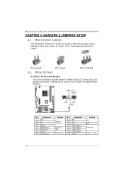
... to set up jumpers. When the jumper cap is placed on pins, the jumper is "close", if not, that means the jumper is "open". Motherboard Manual CHAPTER 3: HEADERS & JUMPERS SETUP 3.1 HOW TO SETUP JUMPERS The illustration shows how to connect the PC case's front panel switch functions.
... to set up jumpers. When the jumper cap is placed on pins, the jumper is "close", if not, that means the jumper is "open". Motherboard Manual CHAPTER 3: HEADERS & JUMPERS SETUP 3.1 HOW TO SETUP JUMPERS The illustration shows how to connect the PC case's front panel switch functions.

Setup Manual
Page 18
This header allows only HD audio front panel connector; Motherboard Manual F_AUDIO1: Front Panel Audio Header This header allows user to connect the PCI bracket SPDIF output header. 13 Pin Assignment 1 +5V 2 SPDIF_OUT 3 Ground 16 AC'97 connector is not acceptable. 2 10 1 9 Pin Assignment 1 Mic Left in 2 Ground 3 Mic Right in 4 GPIO 5 Right line in 6 Jack Sense 7 Front Sense 8 Key 9 Left line in 10 Jack Sense JSPDIFOUT1: Digital Audio-out Connector This connector allows user to connect the front audio output cable with the PC front panel.
This header allows only HD audio front panel connector; Motherboard Manual F_AUDIO1: Front Panel Audio Header This header allows user to connect the PCI bracket SPDIF output header. 13 Pin Assignment 1 +5V 2 SPDIF_OUT 3 Ground 16 AC'97 connector is not acceptable. 2 10 1 9 Pin Assignment 1 Mic Left in 2 Ground 3 Mic Right in 4 GPIO 5 Right line in 6 Jack Sense 7 Front Sense 8 Key 9 Left line in 10 Jack Sense JSPDIFOUT1: Digital Audio-out Connector This connector allows user to connect the front audio output cable with the PC front panel.

Setup Manual
Page 20
JUSBV2: +5V STB for USB ports at F_USB1/F_USB2. JUSBV2: +5V for USB ports at F_USB1/F_USB2. JUSBV1 3 1 3 1 JUSBV2 3 1 Pin 1-2 close 3 1 Pin 2-3 close JKB_PWR: Power Source Header for PS/2 Keyboard and Mouse 3 3 1 1 Pin 1-2 close +5V for PS/2 keyboard and mouse. 3 1 Pin 2-3 close +5V STB for USB ports at USB1/RJ45USB1. Motherboard Manual JUSBV1/JUSBV2: Power Source Headers for USB Ports Pin 1-2 Close: JUSBV1: +5V for USB ports at USB1/RJ45USB1. Pin 2-3 Close: JUSBV1: +5V STB for PS/2 keyboard and mouse. 18
JUSBV2: +5V STB for USB ports at F_USB1/F_USB2. JUSBV2: +5V for USB ports at F_USB1/F_USB2. JUSBV1 3 1 3 1 JUSBV2 3 1 Pin 1-2 close 3 1 Pin 2-3 close JKB_PWR: Power Source Header for PS/2 Keyboard and Mouse 3 3 1 1 Pin 1-2 close +5V for PS/2 keyboard and mouse. 3 1 Pin 2-3 close +5V STB for USB ports at USB1/RJ45USB1. Motherboard Manual JUSBV1/JUSBV2: Power Source Headers for USB Ports Pin 1-2 Close: JUSBV1: +5V for USB ports at USB1/RJ45USB1. Pin 2-3 Close: JUSBV1: +5V STB for PS/2 keyboard and mouse. 18
Setup Manual
Page 22
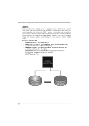
...disk or on a second redundant drive in a RAID 1 array system. Block 1 Block 2 Block 3 20 Block 1 Block 2 Block 3 Motherboard Manual RAID 1: Every read and write is actually carried out in parallel across 2 disk drives in the array. Performance is ideal for small databases or any ...; Benefits: Provides 100% data redundancy. The mirrored (backup) copy of one drive fail, the controller switches to the other application that eliminates tedious manual backups to more expensive and less reliable media. Features and Benefits Drives: Minimum 2, and maximum is 2. Uses: RAID 1 ...
...disk or on a second redundant drive in a RAID 1 array system. Block 1 Block 2 Block 3 20 Block 1 Block 2 Block 3 Motherboard Manual RAID 1: Every read and write is actually carried out in parallel across 2 disk drives in the array. Performance is ideal for small databases or any ...; Benefits: Provides 100% data redundancy. The mirrored (backup) copy of one drive fail, the controller switches to the other application that eliminates tedious manual backups to more expensive and less reliable media. Features and Benefits Drives: Minimum 2, and maximum is 2. Uses: RAID 1 ...

Setup Manual
Page 24
... detailed setup information, please refer to the Driver CD, or go to http://www.nvidia.com/object/IO_28159.html to store the data itself. Motherboard Manual RAID 5: RAID 5 stripes both data and parity information across all the drives in the array.
... detailed setup information, please refer to the Driver CD, or go to http://www.nvidia.com/object/IO_28159.html to store the data itself. Motherboard Manual RAID 5: RAID 5 stripes both data and parity information across all the drives in the array.
Setup Manual
Page 25
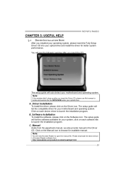
... file SETUP.EXE under your optical drive. Please download the latest version of Acrobat Reader software from the paperback manual, we also provide manual in the Driver CD. The setup guide will list the software available for your motherboard and operating system. The...Reader to launch the installation program. Driver Installation To install the driver, please click on the Manual icon to launch the installation program. A. Click on the Driver icon. MCP6P3/N68S3 CHAPTER 5: USEFUL HELP 5.1 DRIVER INSTALLATION NOTE After you installed your operating system, please insert...
... file SETUP.EXE under your optical drive. Please download the latest version of Acrobat Reader software from the paperback manual, we also provide manual in the Driver CD. The setup guide will list the software available for your motherboard and operating system. The...Reader to launch the installation program. Driver Installation To install the driver, please click on the Manual icon to launch the installation program. A. Click on the Driver icon. MCP6P3/N68S3 CHAPTER 5: USEFUL HELP 5.1 DRIVER INSTALLATION NOTE After you installed your operating system, please insert...
Setup Manual
Page 26
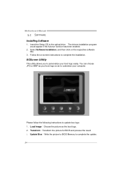
... would appear if the Autorun function has been enabled. 2. You can choose JPG or BMP as your boot logo so as the boot logo. 2. Motherboard Manual 5.2 SOFTWARE Installing Software 1.
... would appear if the Autorun function has been enabled. 2. You can choose JPG or BMP as your boot logo so as the boot logo. 2. Motherboard Manual 5.2 SOFTWARE Installing Software 1.

Setup Manual
Page 28
... check: 1. After confirmed, please follow steps below to avoid a damage of the CPU, and the system may not power on again. Or you can: 1. Motherboard Manual 5.4 EXTRA INFORMATION CPU Overheated If the system shutdown automatically after power on system for seconds. 2. Plug in the power cord and boot up the system...
... check: 1. After confirmed, please follow steps below to avoid a damage of the CPU, and the system may not power on again. Or you can: 1. Motherboard Manual 5.4 EXTRA INFORMATION CPU Overheated If the system shutdown automatically after power on system for seconds. 2. Plug in the power cord and boot up the system...

Setup Manual
Page 46
Motherboard Manual JAPANESE 仕様 Socket AM3 AMD 64 32ビットと64 CPU AMD Phenom II/ Athlon II 能です 95W) 2.0 2.0 GT/s FSB ート2.0 GeForce 6150 SE/nForce 430 (MCP6P3 GeForce 7025/nForce 630a (N68S3) DDR3 DIMM ...DIMM サポート ITE 8718F Super I/O H/Wモニター Super I/O ITE GeForce 6150 SE/nForce 430 (MCP6P3) ス GeForce 7025/nForce 630a (N68S3) 512MBです(under OS) IDE 統合IDE Ultra DMA 33 / ...
Motherboard Manual JAPANESE 仕様 Socket AM3 AMD 64 32ビットと64 CPU AMD Phenom II/ Athlon II 能です 95W) 2.0 2.0 GT/s FSB ート2.0 GeForce 6150 SE/nForce 430 (MCP6P3 GeForce 7025/nForce 630a (N68S3) DDR3 DIMM ...DIMM サポート ITE 8718F Super I/O H/Wモニター Super I/O ITE GeForce 6150 SE/nForce 430 (MCP6P3) ス GeForce 7025/nForce 630a (N68S3) 512MBです(under OS) IDE 統合IDE Ultra DMA 33 / ...
Bios Setup
Page 2
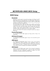
... This PHOENIX-AWARD BIOS supports the Plug and Play Version 1.0A spec ification. MCP6PB M2+/N68S BIOS Setup BIOS Setup Introduction The purpose of this manual is turned off. The rest of the input and output devices such as virus and password protection or chipset fine-tuning options are also included... when the power is to the hard disk drives and video monitors can do without accessing programs from a disk. This system controls most of this manual will to CMOS RAM.
... This PHOENIX-AWARD BIOS supports the Plug and Play Version 1.0A spec ification. MCP6PB M2+/N68S BIOS Setup BIOS Setup Introduction The purpose of this manual is turned off. The rest of the input and output devices such as virus and password protection or chipset fine-tuning options are also included... when the power is to the hard disk drives and video monitors can do without accessing programs from a disk. This system controls most of this manual will to CMOS RAM.

Bios Setup
Page 4
... performance, the BIOS firmware is for your reference only. Advanced BIOS Features This submenu allows you to select from this manual (Figure 1, 2, 3, 4, 5, 6, 7, 8, 9) is being continuously updated. The BIOS information described in this manual. „ Figure 1: Main Menu Standard CMOS Features This submenu contains industry standard configurable options. The actual BIOS information and...
... performance, the BIOS firmware is for your reference only. Advanced BIOS Features This submenu allows you to select from this manual (Figure 1, 2, 3, 4, 5, 6, 7, 8, 9) is being continuously updated. The BIOS information described in this manual. „ Figure 1: Main Menu Standard CMOS Features This submenu contains industry standard configurable options. The actual BIOS information and...
Bios Setup
Page 30
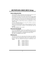
... assigned to the memory locations. If the Enabled option is chosen, the system is forced to update ESCDs and then is called ESCD. By Choosing "Manual", the user will detect the system resources and automatically assign the relative IRQ and DMA channel for add-on cards. When you press the "Press... is chosen, the system's ESCD will allow you to the PCI Bus or provides for the resources controlled by function. The Choices: Auto (ESCD) (default), Manual. The system needs to record and update ESCD to it. If the Disabled (default) option is assigned to the ISA Bus and provides non-PnP...
... assigned to the memory locations. If the Enabled option is chosen, the system is forced to update ESCDs and then is called ESCD. By Choosing "Manual", the user will detect the system resources and automatically assign the relative IRQ and DMA channel for add-on cards. When you press the "Press... is chosen, the system's ESCD will allow you to the PCI Bus or provides for the resources controlled by function. The Choices: Auto (ESCD) (default), Manual. The system needs to record and update ESCD to it. If the Disabled (default) option is assigned to the ISA Bus and provides non-PnP...

