
Setup Manual
Page 1
...contents here without first obtaining the vendor's approval in accordance with the instructions, may cause harmful interference to notify any purpose. G41 DVI Setup Manual FCC Information and Copyright This equipment has been tested and found in this publication, in part or in whole, is no ...not allowed without obligation to radio communications. Duplication of their respective companies. Further the vendor reserves the right to revise this user's manual is subject to Part 15 of the FCC Rules. This equipment generates, uses, and can radiate radio frequency energy and, if not...
...contents here without first obtaining the vendor's approval in accordance with the instructions, may cause harmful interference to notify any purpose. G41 DVI Setup Manual FCC Information and Copyright This equipment has been tested and found in this publication, in part or in whole, is no ...not allowed without obligation to radio communications. Duplication of their respective companies. Further the vendor reserves the right to revise this user's manual is subject to Part 15 of the FCC Rules. This equipment generates, uses, and can radiate radio frequency energy and, if not...

Setup Manual
Page 3
...computer from power outlet before operation. „ Before you for ATX Case X 1 Installation Guide X 1 Fully Setup Driver CD X 1 (full version manual files inside the case after installation. Hold the board on the edge, do not try to bend or flex the board. „ Do not leave...to 45 degrees Celsius. 1.2 PACKAGE CHECKLIST HDD Cable X 1 Serial ATA Cable X 1 Rear I/O Panel for choosing our product. CHAPTER 1: INTRODUCTION G41 DVI 1.1 BEFORE YOU START Thank you take the motherboard out from anti-static bag, ground yourself properly by touching any unfastened small parts inside ) FDD ...
...computer from power outlet before operation. „ Before you for ATX Case X 1 Installation Guide X 1 Fully Setup Driver CD X 1 (full version manual files inside the case after installation. Hold the board on the edge, do not try to bend or flex the board. „ Do not leave...to 45 degrees Celsius. 1.2 PACKAGE CHECKLIST HDD Cable X 1 Serial ATA Cable X 1 Rear I/O Panel for choosing our product. CHAPTER 1: INTRODUCTION G41 DVI 1.1 BEFORE YOU START Thank you take the motherboard out from anti-static bag, ground yourself properly by touching any unfastened small parts inside ) FDD ...

Setup Manual
Page 4
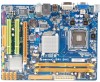
Motherboard Manual 1.3 MOTHERBOARD FEATURES SPEC LGA 775 Supports Hyper-Threading / Execute Disable Bit / Intel Core2Duo / Core2Quad / Enhanced Intel SpeedStep® / Intel Architecture-64 / CPU Pentium Dual-Core / Celeron Dual-Core / Extended Memory 64 Technology / Virtualization Celeron 4xx processor Technology (Maximum Watt: 95W) FSB Support 800 / 1066 / 1333 MHz Chipset Intel G41 Intel ICH7...
Motherboard Manual 1.3 MOTHERBOARD FEATURES SPEC LGA 775 Supports Hyper-Threading / Execute Disable Bit / Intel Core2Duo / Core2Quad / Enhanced Intel SpeedStep® / Intel Architecture-64 / CPU Pentium Dual-Core / Celeron Dual-Core / Extended Memory 64 Technology / Virtualization Celeron 4xx processor Technology (Maximum Watt: 95W) FSB Support 800 / 1066 / 1333 MHz Chipset Intel G41 Intel ICH7...

Setup Manual
Page 6
J CM O S1 BI O S SATA4 SATA3 SATA2 SATA1 4 Motherboard Manual 1.5 MOTHERBOARD LAYOUT KBMS1 LGA775 VGA1 ATXPWR2 CPU1 CPU_FAN1 ATXPWR1 D D R 2_A 1 D D R 2_B 1 DVI1 JUSBV1 USB1 LAN RJ45USB1 Intel G41 IDE1 AUDIO1 F_AUDIO1 CD_IN1 BAT1 F_CO M 1 Super I/O SPDIF 1 PEX16_1 PCI1 Intel ICH7 Codec F_PRINT1 PCI2 FDD1 JUSBV2 SYS _FA N1 F_USB1 F_USB2 PANEL1 Note: ■ represents the 1st pin.
J CM O S1 BI O S SATA4 SATA3 SATA2 SATA1 4 Motherboard Manual 1.5 MOTHERBOARD LAYOUT KBMS1 LGA775 VGA1 ATXPWR2 CPU1 CPU_FAN1 ATXPWR1 D D R 2_A 1 D D R 2_B 1 DVI1 JUSBV1 USB1 LAN RJ45USB1 Intel G41 IDE1 AUDIO1 F_AUDIO1 CD_IN1 BAT1 F_CO M 1 Super I/O SPDIF 1 PEX16_1 PCI1 Intel ICH7 Codec F_PRINT1 PCI2 FDD1 JUSBV2 SYS _FA N1 F_USB1 F_USB2 PANEL1 Note: ■ represents the 1st pin.

Setup Manual
Page 8
Connect the CPU FAN power cable into the CPU_FAN1. Step 4: Put the CPU Fan and heatsink assembly on the CPU and buckle it on CPU should point forwards this triangular cut edge. This completes the installation. 6 Motherboard Manual Step 2: Look for the triangular cut edge on socket, and the golden dot on the retention frame. The CPU will fit only in the correct orientation. Step 2-1: Step 2-2: Step 3: Hold the CPU down firmly, and then lower the lever to locked position to complete the installation.
Connect the CPU FAN power cable into the CPU_FAN1. Step 4: Put the CPU Fan and heatsink assembly on the CPU and buckle it on CPU should point forwards this triangular cut edge. This completes the installation. 6 Motherboard Manual Step 2: Look for the triangular cut edge on socket, and the golden dot on the retention frame. The CPU will fit only in the correct orientation. Step 2-1: Step 2-2: Step 3: Hold the CPU down firmly, and then lower the lever to locked position to complete the installation.

Setup Manual
Page 10
Unlock a DIMM slot by pressing the retaining clips outward. DD R2_A1 DD R2_B1 Motherboard Manual 2.3 INSTALLING SYSTEM MEMORY A. Align a DIMM on the slot such that the notch on the DIMM matches the break on the Slot. 2. Insert the DIMM vertically and firmly into the slot until the retaining chip snap back in place and the DIMM is properly seated. 8 DDR2 module 1.
Unlock a DIMM slot by pressing the retaining clips outward. DD R2_A1 DD R2_B1 Motherboard Manual 2.3 INSTALLING SYSTEM MEMORY A. Align a DIMM on the slot such that the notch on the DIMM matches the break on the Slot. 2. Insert the DIMM vertically and firmly into the slot until the retaining chip snap back in place and the DIMM is properly seated. 8 DDR2 module 1.

Setup Manual
Page 12
SATA 4 SATA 3 SATA 2 SATA 1 Pin Assignment 1 Ground 2 TX+ 3 TX4 Ground 5 RX6 RX+ 7 Ground 14 7 10 Motherboard Manual 2.4 CONNECTORS AND SLOTS FDD1: Floppy Disk Connector The motherboard provides a standard floppy disk connector that supports 360K, 720K, 1.2M, 1.44M and 2.88M floppy disk types. 2 ...
SATA 4 SATA 3 SATA 2 SATA 1 Pin Assignment 1 Ground 2 TX+ 3 TX4 Ground 5 RX6 RX+ 7 Ground 14 7 10 Motherboard Manual 2.4 CONNECTORS AND SLOTS FDD1: Floppy Disk Connector The motherboard provides a standard floppy disk connector that supports 360K, 720K, 1.2M, 1.44M and 2.88M floppy disk types. 2 ...

Setup Manual
Page 14
Maximum theoretical realized bandwidth of 4GB/s simultaneously per direction, for expansion cards. This PCI slot is equipped with 2 standard PCI slots. Motherboard Manual PEX16_1: PCI-Express x16 Slot - PCI-Express supports a raw bit-rate of 8GB/s totally. - PEX16_1 PCI1/PCI2: Peripheral Component Interconnect Slots This motherboard is designated ...
Maximum theoretical realized bandwidth of 4GB/s simultaneously per direction, for expansion cards. This PCI slot is equipped with 2 standard PCI slots. Motherboard Manual PEX16_1: PCI-Express x16 Slot - PCI-Express supports a raw bit-rate of 8GB/s totally. - PEX16_1 PCI1/PCI2: Peripheral Component Interconnect Slots This motherboard is designated ...

Setup Manual
Page 16
... on the PC front panel, and also can be connected with internal USB devices, like USB card reader. Set the jumper to "Pin 2-3 close ". 5. Motherboard Manual F_USB1/F_USB2: Headers for five seconds. 4. Remove AC power line. 2. Power on pin2-3 allows user to avoid damaging the motherboard. 13 Pin 1-2 Close: Normal Operation...
... on the PC front panel, and also can be connected with internal USB devices, like USB card reader. Set the jumper to "Pin 2-3 close ". 5. Motherboard Manual F_USB1/F_USB2: Headers for five seconds. 4. Remove AC power line. 2. Power on pin2-3 allows user to avoid damaging the motherboard. 13 Pin 1-2 Close: Normal Operation...

Setup Manual
Page 18
Motherboard Manual JUSBV1/JUSBV2: Power Source Headers for USB Ports Pin 1-2 Close: JUSBV1: +5V for USB ports at F_USB1/F_USB2. JUSBV2: +5V for USB ports at USB1/...
Motherboard Manual JUSBV1/JUSBV2: Power Source Headers for USB Ports Pin 1-2 Close: JUSBV1: +5V for USB ports at F_USB1/F_USB2. JUSBV2: +5V for USB ports at USB1/...

Setup Manual
Page 20
... B. You will see the following window after you insert the CD The setup guide will list the compatible driver for your optical drive. Manual Aside from http://www.adobe.com /produ cts/a crobat /reads tep2 .html 18 Note: You will list the software available for your motherboard...To install the software, please click on the Driver icon. Please download the latest version of Acrobat Reader software from the paperback manual, we also provide manual in the Driver CD. The setup guide will auto detect your motherboard and operating system. Click on each device driver to ...
... B. You will see the following window after you insert the CD The setup guide will list the compatible driver for your optical drive. Manual Aside from http://www.adobe.com /produ cts/a crobat /reads tep2 .html 18 Note: You will list the software available for your motherboard...To install the software, please click on the Driver icon. Please download the latest version of Acrobat Reader software from the paperback manual, we also provide manual in the Driver CD. The setup guide will auto detect your motherboard and operating system. Click on each device driver to ...

Setup Manual
Page 22
Motherboard Manual After filling up this information to a .txt file, click "Save As..." and then you will be saved to the following web http://www.biostar.com.tw/app/en-us/about/contact.php for your system information including motherboard/BIOS/CPU/video/ device/OS information. Go to a .txt file. Your ...
Motherboard Manual After filling up this information to a .txt file, click "Save As..." and then you will be saved to the following web http://www.biostar.com.tw/app/en-us/about/contact.php for your system information including motherboard/BIOS/CPU/video/ device/OS information. Go to a .txt file. Your ...

Setup Manual
Page 24
... BIOS procedure; While the system boots up and the full screen logo shows, press key to skip this procedure. Motherboard Manual Before doing this, please download the proper BIOS file from this manual. 22 The utility will show for asking you backup current BIOS. In the BIOS setup, use the Load Optimized...
... BIOS procedure; While the system boots up and the full screen logo shows, press key to skip this procedure. Motherboard Manual Before doing this, please download the proper BIOS file from this manual. 22 The utility will show for asking you backup current BIOS. In the BIOS setup, use the Load Optimized...

Setup Manual
Page 26
... contains the BIOS file and press to perform the BIOS update process. 6. Select the proper BIOS file and press then to enter the utility. 5. Motherboard Manual BIO-Flasher BIO-Flasher is built in the BIOS chip. Insert the USB pen drive or the floppy disk that contains the BIOS file to...
... contains the BIOS file and press to perform the BIOS update process. 6. Select the proper BIOS file and press then to enter the utility. 5. Motherboard Manual BIO-Flasher BIO-Flasher is built in the BIOS chip. Insert the USB pen drive or the floppy disk that contains the BIOS file to...

Setup Manual
Page 28
... correct drive types. Keyboard lights Using even pressure on both ends are capable of the power supply does not 2. Set master/slave jumpers correctly. Motherboard Manual 4.5 TROUBLESHOOTING Probable Solution 1. System is no power in ; All hard disks are securely plugged in the system. 1. Reformat the hard drive. work...
... correct drive types. Keyboard lights Using even pressure on both ends are capable of the power supply does not 2. Set master/slave jumpers correctly. Motherboard Manual 4.5 TROUBLESHOOTING Probable Solution 1. System is no power in ; All hard disks are securely plugged in the system. 1. Reformat the hard drive. work...

Bios Setup
Page 1
G41 DVI BIOS Manual BIOS Setup 1 1 Main Menu 3 2 Advanced Menu 7 3 PCIPnP Menu 18 4 Boot Menu 23 5 Chipset Menu 26 6 Performance Menu 31 7 Exit Menu 34 i
G41 DVI BIOS Manual BIOS Setup 1 1 Main Menu 3 2 Advanced Menu 7 3 PCIPnP Menu 18 4 Boot Menu 23 5 Chipset Menu 26 6 Performance Menu 31 7 Exit Menu 34 i

Bios Setup
Page 2
...Advanced Configuration and Power interface specifi cation (ACPI). Plug and Pla y Support T his AMI BIOS supports Version 1.03 of this manual will to describe the settings in the ACPI specification, developed by a battery so that it retains theSetup information when the power is to ...power of CMOS RAM is supplied by Microso ft, Intel and T oshiba. 1 Power management features are supported. G41 DVI BIOS Manual BIOS Setup Introduction T he purpose of this manual is turned off. Some additional features, such as virus and password prot ection or chipset fine-tuning options are ...
...Advanced Configuration and Power interface specifi cation (ACPI). Plug and Pla y Support T his AMI BIOS supports Version 1.03 of this manual will to describe the settings in the ACPI specification, developed by a battery so that it retains theSetup information when the power is to ...power of CMOS RAM is supplied by Microso ft, Intel and T oshiba. 1 Power management features are supported. G41 DVI BIOS Manual BIOS Setup Introduction T he purpose of this manual is turned off. Some additional features, such as virus and password prot ection or chipset fine-tuning options are ...

Bios Setup
Page 3
.... z For better system perform ance, the BIOS firmware is supported. General Help Navigation Keys Notice z T he BIOS information described in this user's manual and any settings, please load the default settings to ensure system's compatibility and stability. T he default BIOS settings apply for most conditions to be slightly... Using Setup When starting up the computer, press during the Power-On Self-Test (POST) to select item and ch ange the settings. G41 DVI BIOS Manual PCI Bus Support T his AMI BIOS supports the Intel CPU. Navigation Keys for your reference only.
.... z For better system perform ance, the BIOS firmware is supported. General Help Navigation Keys Notice z T he BIOS information described in this user's manual and any settings, please load the default settings to ensure system's compatibility and stability. T he default BIOS settings apply for most conditions to be slightly... Using Setup When starting up the computer, press during the Power-On Self-Test (POST) to select item and ch ange the settings. G41 DVI BIOS Manual PCI Bus Support T his AMI BIOS supports the Intel CPU. Navigation Keys for your reference only.

Bios Setup
Page 4
..., VGA shard memory will appear on :01.01.0 1 Build Date:01/01/0 9 Syste m Memory Size : Use [ENTER], [TA B] or [ SHIFT-TAB] t o sele ct a field. G41 DVI BIOS Manual 1 Main Menu Once you set the date. 3 System Time Set the system internal clock. Syste m Time Syste m Date Flopp y A > IDE Configuratio n [ 00:00:00 ] [ Thu...
..., VGA shard memory will appear on :01.01.0 1 Build Date:01/01/0 9 Syste m Memory Size : Use [ENTER], [TA B] or [ SHIFT-TAB] t o sele ct a field. G41 DVI BIOS Manual 1 Main Menu Once you set the date. 3 System Time Set the system internal clock. Syste m Time Syste m Date Flopp y A > IDE Configuratio n [ 00:00:00 ] [ Thu...

Bios Setup
Page 5
...] [ Disabled] [ 35] Options Disa bled Comp atible Enha nced S elect Screen S elect Item En terG o to enter the sub-menu of ID E/SAT A devices. G41 DVI BIOS Manual Floppy A Select the type of floppy disk drive installed in / None IDE Configuration T he BIOS will automatically detect the presence of detailed options. Options: 360K...
...] [ Disabled] [ 35] Options Disa bled Comp atible Enha nced S elect Screen S elect Item En terG o to enter the sub-menu of ID E/SAT A devices. G41 DVI BIOS Manual Floppy A Select the type of floppy disk drive installed in / None IDE Configuration T he BIOS will automatically detect the presence of detailed options. Options: 360K...

