
User Guide
Page 58
Defining Calibration Grid A calibration grid is generated along the positive direction of the X and Y axis. Click the button in the lower-left corner, and the grid is helpful when calibrating images covered ...
Defining Calibration Grid A calibration grid is generated along the positive direction of the X and Y axis. Click the button in the lower-left corner, and the grid is helpful when calibrating images covered ...
User Guide
Page 87
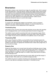
... Blue components. Using the specific criterion the program defines which pixels of the original (color or grayscale) image should become white (background pixels), and then generates a monochrome image and places it converts pixels below this method, you can define a range half-length. Binarization methods To convert color and grayscale images to...
... Blue components. Using the specific criterion the program defines which pixels of the original (color or grayscale) image should become white (background pixels), and then generates a monochrome image and places it converts pixels below this method, you can define a range half-length. Binarization methods To convert color and grayscale images to...
User Guide
Page 103
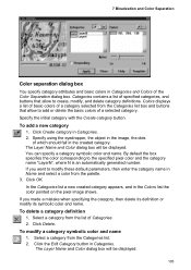
... a category selected from the Categories list box and buttons that allow to the specified pixel color and the category name "LayerN", where N is an automatically generated number. Categories contains a list of specified categories, and buttons that allow to create, modify, and delete category definitions. Colors displays a list of basic colors of...
... a category selected from the Categories list box and buttons that allow to the specified pixel color and the category name "LayerN", where N is an automatically generated number. Categories contains a list of specified categories, and buttons that allow to create, modify, and delete category definitions. Colors displays a list of basic colors of...

User Guide
Page 164
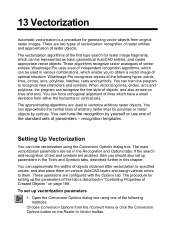
... raster lines on the technology of local recognition of vector areas. Using this technology, the program identifies raster lines as lines, arcs, or circles, and generates the appropriate vector objects.
... raster lines on the technology of local recognition of vector areas. Using this technology, the program identifies raster lines as lines, arcs, or circles, and generates the appropriate vector objects.
User Guide
Page 171
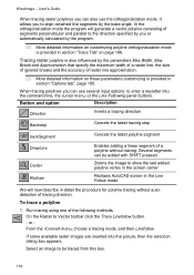
... without autodetection of the following methods: On the Raster to show the last added polyline vertex in the screen center Redraws AutoCAD screen in the Line Follow mode We will generate a vector polyline consisting of raster line approximation. * More detailed information on these parameters customizing is provided in section "Trace Tab" on...
... without autodetection of the following methods: On the Raster to show the last added polyline vertex in the screen center Redraws AutoCAD screen in the Line Follow mode We will generate a vector polyline consisting of raster line approximation. * More detailed information on these parameters customizing is provided in section "Trace Tab" on...

User Guide
Page 174
...on reaching a node, the program tries to determine the trace direction, and draws a mark on the suggested raster line extension (AutoCAD-style cross of the current color), and the following prompt appears in the command line: [Direction/Backstep/backSegment/drawLine/pan2Center/Redraw/...and once selected, tracing will continue operating in the Trace tab of Conversion Options dialog. This interval is located close to cancel generation of polyline segments, obtained during polyline tracing. WiseImage automatically stops tracing a polyline, if the latest created polyline segment crosses any...
...on reaching a node, the program tries to determine the trace direction, and draws a mark on the suggested raster line extension (AutoCAD-style cross of the current color), and the following prompt appears in the command line: [Direction/Backstep/backSegment/drawLine/pan2Center/Redraw/...and once selected, tracing will continue operating in the Trace tab of Conversion Options dialog. This interval is located close to cancel generation of polyline segments, obtained during polyline tracing. WiseImage automatically stops tracing a polyline, if the latest created polyline segment crosses any...
User Guide
Page 182
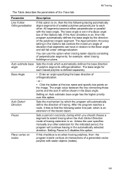
... raster objects (nodes). 187 Place vertex on the image. After the program reaches a node, it tries to find the following tracing automatically aligns segments of a generated vector polyline with the base angle. 12 Tracing The Table describes the parameters of orthogonalization. - Unless the user specifies manually any other . The Approximation Accuracy...
... raster objects (nodes). 187 Place vertex on the image. After the program reaches a node, it tries to find the following tracing automatically aligns segments of a generated vector polyline with the base angle. 12 Tracing The Table describes the parameters of orthogonalization. - Unless the user specifies manually any other . The Approximation Accuracy...

User Guide
Page 183
...correct results of assignment of objects widths during vectorization in the case where the width of raster lines does not exceed 2.11 AutoCAD units, as the Lineweight parameter can control the properties of created vector objects: calibrate the widths of obtained vector objects, place... Properties of Created Objects When creating vectors by tracing (and also with the automatic vectorization procedure in the range 0 to the generated vector objects. User's Guide Parameter Auto Extend vectors Export single contour Description This feature simplifies forced selection and tracing of arcs and...
...correct results of assignment of objects widths during vectorization in the case where the width of raster lines does not exceed 2.11 AutoCAD units, as the Lineweight parameter can control the properties of created vector objects: calibrate the widths of obtained vector objects, place... Properties of Created Objects When creating vectors by tracing (and also with the automatic vectorization procedure in the range 0 to the generated vector objects. User's Guide Parameter Auto Extend vectors Export single contour Description This feature simplifies forced selection and tracing of arcs and...
User Guide
Page 189
... button on lines and arcs. If the search and recognition of independent recognition algorithms, which can be represented as basic geometrical AutoCAD entities, and create appropriate vector objects. To set of text and symbols are configured with the Options tab. These operations are...box using the Conversion Options dialog box. You can be used to obtain a vector image of the first type search for generating vector objects from either the horizontal or vertical axis. The vectorization algorithms of optimal structure. The main vectorization parameters are used in...
... button on lines and arcs. If the search and recognition of independent recognition algorithms, which can be represented as basic geometrical AutoCAD entities, and create appropriate vector objects. To set of text and symbols are configured with the Options tab. These operations are...box using the Conversion Options dialog box. You can be used to obtain a vector image of the first type search for generating vector objects from either the horizontal or vertical axis. The vectorization algorithms of optimal structure. The main vectorization parameters are used in...

User Guide
Page 190
...you need to vectorize maps or schemes the use various sets of polylines woukd be used for raster image vectorization. to use of AutoCAD entities. To get access to the hidden additional parameters of the algorithm, click on the necessary algorithm, you can select a set ...then click OK. in this tab you need to vectorize engineering drawings you should use algorithms that recognize raster analogues of vector entities and generate approximating vector objects of arbitrary form; For example, to set of the vectorization algorithms, that create lines, circles, arcs - On the...
...you need to vectorize maps or schemes the use various sets of polylines woukd be used for raster image vectorization. to use of AutoCAD entities. To get access to the hidden additional parameters of the algorithm, click on the necessary algorithm, you can select a set ...then click OK. in this tab you need to vectorize engineering drawings you should use algorithms that recognize raster analogues of vector entities and generate approximating vector objects of arbitrary form; For example, to set of the vectorization algorithms, that create lines, circles, arcs - On the...

User Guide
Page 197
...ÞNOTE: This list contains definitions of text area searches. The text areas will be only horizontal. If this option can generate only words which the program recognizes the characters of the English alphabet, digits, punctuation marks and special characters (the first half ...of the word characters is recognized, then the OCR does not generate a text object. defines the accepted raster text operation. This list contains definitions of the created texts are calculated. Only Standalone Letters...
...ÞNOTE: This list contains definitions of text area searches. The text areas will be only horizontal. If this option can generate only words which the program recognizes the characters of the English alphabet, digits, punctuation marks and special characters (the first half ...of the word characters is recognized, then the OCR does not generate a text object. defines the accepted raster text operation. This list contains definitions of the created texts are calculated. Only Standalone Letters...
User Guide
Page 198
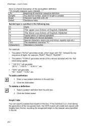
... texts, the OCR module will create text objects with the first letter being capital. Ÿ " %D %% " will generate: "20 % ", " 1100 % ", " 12.50 % ", etc. Ÿ "%DV" will generate: "5V", "220V", "13.8V", etc. Select a pattern definition from this box. Height Table You can specify possible... text heights in the edit box. 2. WiseImage - To add a definition 1. User's Guide Here is on, then during the generation of the national alphabet with heights from the edit box. 2. If the checkbox is a formal description of character sequence definition [length] Any ...
... texts, the OCR module will create text objects with the first letter being capital. Ÿ " %D %% " will generate: "20 % ", " 1100 % ", " 12.50 % ", etc. Ÿ "%DV" will generate: "5V", "220V", "13.8V", etc. Select a pattern definition from this box. Height Table You can specify possible... text heights in the edit box. 2. WiseImage - To add a definition 1. User's Guide Here is on, then during the generation of the national alphabet with heights from the edit box. 2. If the checkbox is a formal description of character sequence definition [length] Any ...
User Guide
Page 217
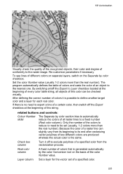
... Export to define another target color and a layer for the vector set (usually, 1-2 colors more than the real number). Check box column Turn it is generated automatically by color checkbox. Layer column Set a layer for each real color. 13 Vectorization Visually check the quality of the recognized objects, their color and...
... Export to define another target color and a layer for the vector set (usually, 1-2 colors more than the real number). Check box column Turn it is generated automatically by color checkbox. Layer column Set a layer for each real color. 13 Vectorization Visually check the quality of the recognized objects, their color and...