
User Manual
Page 1
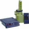
Programmable Antenna Rotator VH126N User's Manual Unpacking Make sure the following pieces are in the box: (1) Drive unit (1) Control unit (1) Remote control Hardware kit: (2) U Bolts (4) Threaded inserts (3) U Bolt brackets (1) ...-jacketed lead and connect it to the drive unit 1. IMPORTANT: Make sure there are snug against the drive unit. 3. CAUTION: Select a mounting location where the antenna cannot come in place. 4. One end of the inserts to grip the mast securely. Make sure you 'll need to mount it stops on the...
Programmable Antenna Rotator VH126N User's Manual Unpacking Make sure the following pieces are in the box: (1) Drive unit (1) Control unit (1) Remote control Hardware kit: (2) U Bolts (4) Threaded inserts (3) U Bolt brackets (1) ...-jacketed lead and connect it to the drive unit 1. IMPORTANT: Make sure there are snug against the drive unit. 3. CAUTION: Select a mounting location where the antenna cannot come in place. 4. One end of the inserts to grip the mast securely. Make sure you 'll need to mount it stops on the...

User Manual
Page 2
... two holes of the jacket off insulators (not included) as shown below. Step 3: Install the antenna/cable 1. After connecting the antenna lead-in cable to the support mast with attached lock washers on connector. Tape the rotator control cable directly to that length. 2. Tighten the nuts. Turn on the front panel reads 0, and...
... two holes of the jacket off insulators (not included) as shown below. Step 3: Install the antenna/cable 1. After connecting the antenna lead-in cable to the support mast with attached lock washers on connector. Tape the rotator control cable directly to that length. 2. Tighten the nuts. Turn on the front panel reads 0, and...

User Manual
Page 3
...initial setup. If this reset procedure doesn't get the desired results, the antenna of the control unit's remote control has a chart for recording the channel and antenna position corresponding to make sure the rotator goes the entire 360º with no problems. See the Learning section below...front panel to prepare for the next TV station. When the CHANNEL and POSITION indicators stops blinking, the control unit and rotator are initializing to move the antenna clockwise (>) and counter-clockwise ( or < keys on the control unit's front panel keypad. Step 2: Program the control...
...initial setup. If this reset procedure doesn't get the desired results, the antenna of the control unit's remote control has a chart for recording the channel and antenna position corresponding to make sure the rotator goes the entire 360º with no problems. See the Learning section below...front panel to prepare for the next TV station. When the CHANNEL and POSITION indicators stops blinking, the control unit and rotator are initializing to move the antenna clockwise (>) and counter-clockwise ( or < keys on the control unit's front panel keypad. Step 2: Program the control...

User Manual
Page 4
...16, Mississauga, Ontario L5T 3A5 © 2008 Audiovox Accessories Corporation 111 Congressional Blvd., Suite 350 Carmel, IN 46032 VH126N US IB 00 Trademark(s) ® Registered Made in the original packaging is to keep the antenna positions and program locations synchronized. Simultaneously press and ...Company at the same time. alkaline, standard or rechargeable). Performing the Learning Procedure 1. The ANT POSITION indicator displays the rotator cycle time. Turn off . 5. ANY IMPLIED WARRANTIES, INCLUDING ANY IMPLIED WARRANTY OF MERCHANTABILITY OR FITNESS FOR A PARTICULAR...
...16, Mississauga, Ontario L5T 3A5 © 2008 Audiovox Accessories Corporation 111 Congressional Blvd., Suite 350 Carmel, IN 46032 VH126N US IB 00 Trademark(s) ® Registered Made in the original packaging is to keep the antenna positions and program locations synchronized. Simultaneously press and ...Company at the same time. alkaline, standard or rechargeable). Performing the Learning Procedure 1. The ANT POSITION indicator displays the rotator cycle time. Turn off . 5. ANY IMPLIED WARRANTIES, INCLUDING ANY IMPLIED WARRANTY OF MERCHANTABILITY OR FITNESS FOR A PARTICULAR...

User Manual
Page 5
... building in as straight a line as possible to the chimney, roof, or side of the point where it performs. A good practice is to the antenna's lead-in and metal guy wires away from wires, powerlines, and trees: 1. FOLLOW THESE RULES AND LIVE 1. If possible, find a mounting place...Grounded interior metal cold water pipe within five feet of the house. They will remove it yourself. Make sure that the FCC limits your antenna system must be properly grounded. 1. Measure the length of where you cannot maintain this total for safety and performance. If you start to ...
... building in as straight a line as possible to the chimney, roof, or side of the point where it performs. A good practice is to the antenna's lead-in and metal guy wires away from wires, powerlines, and trees: 1. FOLLOW THESE RULES AND LIVE 1. If possible, find a mounting place...Grounded interior metal cold water pipe within five feet of the house. They will remove it yourself. Make sure that the FCC limits your antenna system must be properly grounded. 1. Measure the length of where you cannot maintain this total for safety and performance. If you start to ...


