Installation Manual
Page 2
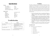
Specifications General Power Supply Power Consumption Current Draw Audio Power Output Operating Temperature Range DC12V
Specifications General Power Supply Power Consumption Current Draw Audio Power Output Operating Temperature Range DC12V
Installation Manual
Page 3
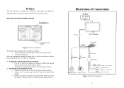
... protective plastic from the doubled sided tape on the chosen location. 2 Illustration of Connections Cable Plug for Navigation Navigation Computer Connector LCD Monitor Connector Control Box Connector Connector Connector Filter Box Interior camera Rearview camera Fuse Red Black Blue Green Fused +12V Constant Ground/Shield Ignition +12V Source Reverse Switch Figure 4. Backside of the...
... protective plastic from the doubled sided tape on the chosen location. 2 Illustration of Connections Cable Plug for Navigation Navigation Computer Connector LCD Monitor Connector Control Box Connector Connector Connector Filter Box Interior camera Rearview camera Fuse Red Black Blue Green Fused +12V Constant Ground/Shield Ignition +12V Source Reverse Switch Figure 4. Backside of the...
Installation Manual
Page 4
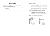
...maintain its condition and performance by following the procedures below . 4. Control BOX To Control BOX Cam Button Selector Switch To Rearview Camera To Interior Camera To LCD monitor To Filter BOX Filter BOX Red (+12V) Blue (Ignition) Black (GND) Green (Reverse) Figure 2. Maintenance Though your system... away from the display. • To avoid damage, do not place external devices or other objects on the top of the monitor. • Occasionally wipe the monitor with ignition on) d) Green wire - Attach the 4 wires in the reverse gear) WARNING: Observe polarity when connecting the wires...
...maintain its condition and performance by following the procedures below . 4. Control BOX To Control BOX Cam Button Selector Switch To Rearview Camera To Interior Camera To LCD monitor To Filter BOX Filter BOX Red (+12V) Blue (Ignition) Black (GND) Green (Reverse) Figure 2. Maintenance Though your system... away from the display. • To avoid damage, do not place external devices or other objects on the top of the monitor. • Occasionally wipe the monitor with ignition on) d) Green wire - Attach the 4 wires in the reverse gear) WARNING: Observe polarity when connecting the wires...
Installation Manual
Page 5
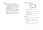
... connections for Audiovox Navigation only. Set the Cam Button selector switch on the control box to the AV-2 position. CAMERA SWITCH 1). Set the Cam Button selector switch on the control box to the rear camera and plug the 4-pin male connector into the control box (AVin-1 location). LCM45NB Monitor Controls and Indicators A: 4.5" TFT color LCD B: Speaker...
... connections for Audiovox Navigation only. Set the Cam Button selector switch on the control box to the AV-2 position. CAMERA SWITCH 1). Set the Cam Button selector switch on the control box to the rear camera and plug the 4-pin male connector into the control box (AVin-1 location). LCM45NB Monitor Controls and Indicators A: 4.5" TFT color LCD B: Speaker...
