

User Guide
Page 13
Z10PH-D16 specifications summary Onboard I/O Connectors Rear I/O Connectors Management Solution Monitoring Environment TPM Header PSU Connector Management Connector USB Connectors Fan Header SMBus Chassis Intruder Front LAN LED Serial Port Header Device Power Connector M.2 Connector External USB Port VGA Port ... KVM-over-Internet P P Operation temperature: 10°C ~ 35°C Non operation temperature: -40°C ~ 70°C Non operation humidity: 20% ~ 90% ( Non condensing) *Refer to ASUS Server AVL for latest update. **Specifications are subject to change without notice. xiii
Z10PH-D16 specifications summary Onboard I/O Connectors Rear I/O Connectors Management Solution Monitoring Environment TPM Header PSU Connector Management Connector USB Connectors Fan Header SMBus Chassis Intruder Front LAN LED Serial Port Header Device Power Connector M.2 Connector External USB Port VGA Port ... KVM-over-Internet P P Operation temperature: 10°C ~ 35°C Non operation temperature: -40°C ~ 70°C Non operation humidity: 20% ~ 90% ( Non condensing) *Refer to ASUS Server AVL for latest update. **Specifications are subject to change without notice. xiii
User Guide
Page 23
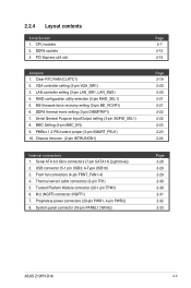
... Trusted Platform Module connector (20-1 pin TPM1) 6. M.2 (NGFF) connector (NGFF1) 7. LAN controller setting (3-pin LAN_SW1, LAN_SW2) 4. PMBus 1.2 PSU select jumper (3-pin SMART_PSU1) 10. PCI Express x24 slot Jumpers 1. Clear RTC RAM (CLRTC1) 2. Chassis Intrusion (2-pin INTRUSION1) Internal connectors 1. Front...2-20 2-20 2-21 2-21 2-22 2-22 2-23 2-23 2-24 Page 2-28 2-29 2-29 2-30 2-30 2-31 2-32 2-33 ASUS Z10PH-D16 2-5 RAID configuration utility selection (3-pin RAID_SEL1) 5. DDR4 sockets 3. USB connector (5-1 pin USB3; ME firmware force recovery setting (3-pin ME_RCVR1) ...
... Trusted Platform Module connector (20-1 pin TPM1) 6. M.2 (NGFF) connector (NGFF1) 7. LAN controller setting (3-pin LAN_SW1, LAN_SW2) 4. PMBus 1.2 PSU select jumper (3-pin SMART_PSU1) 10. PCI Express x24 slot Jumpers 1. Clear RTC RAM (CLRTC1) 2. Chassis Intrusion (2-pin INTRUSION1) Internal connectors 1. Front...2-20 2-20 2-21 2-21 2-22 2-22 2-23 2-23 2-24 Page 2-28 2-29 2-29 2-30 2-30 2-31 2-32 2-33 ASUS Z10PH-D16 2-5 RAID configuration utility selection (3-pin RAID_SEL1) 5. DDR4 sockets 3. USB connector (5-1 pin USB3; ME firmware force recovery setting (3-pin ME_RCVR1) ...

User Guide
Page 41
Set to pins 1-2 for PMBus, set to select PSU PMBus version. PMBus 1.2 PSU select jumper (3-pin SMART_PSU1) This jumper allows you to enable or disable the ASMB8. 9. ASUS Z10PH-D16 2-23 8. BMC Setting (3-pin BMC_EN) This jumper allows you to pins 2-3 for others.
Set to pins 1-2 for PMBus, set to select PSU PMBus version. PMBus 1.2 PSU select jumper (3-pin SMART_PSU1) This jumper allows you to enable or disable the ASMB8. 9. ASUS Z10PH-D16 2-23 8. BMC Setting (3-pin BMC_EN) This jumper allows you to pins 2-3 for others.

User Guide
Page 50
...Orient the connectors and push down firmly until they completely fit. DO NOT connect other 4-pin power connectors of the power supply unit (PSU) to fit these connectors in only one orientation. The power supply plugs are for hard disk drives power supply. The system may become ...(20-pin PWR1, 4-pin PWR2) These connectors are designed to this connector. • Use of a PSU with a higher power output is inadequate. • USE ONLY THE PROPRIETARY POWER SUPPLY and ensure that your PSU can provide at least the minimum power required by your system. 2-32 Chapter 2: Hardware information
...Orient the connectors and push down firmly until they completely fit. DO NOT connect other 4-pin power connectors of the power supply unit (PSU) to fit these connectors in only one orientation. The power supply plugs are for hard disk drives power supply. The system may become ...(20-pin PWR1, 4-pin PWR2) These connectors are designed to this connector. • Use of a PSU with a higher power output is inadequate. • USE ONLY THE PROPRIETARY POWER SUPPLY and ensure that your PSU can provide at least the minimum power required by your system. 2-32 Chapter 2: Hardware information