
Users Manual English
Page 1
WS C246 PRO Motherboard
WS C246 PRO Motherboard

Users Manual English
Page 3
Contents Safety information...vi About this guide...vii WS C246 PRO specifications summary ix Package contents...xi Installation tools and components xii Chapter 1: Product Introduction 1.1 Motherboard overview 1-1 1.1.1 Before you proceed 1-1 1.1.2 Motherboard layout 1-2 1.1.3 Central Processing Unit (CPU 1-4 1.1.4 System memory 1-5 1.1.5 Expansion slots 1-7 1.1.6 Onboard buttons and switches 1-9 1.1.7 Jumpers 1-10 1.1.8 Onboard LEDs 1-11 1.1.9 Internal connectors 1-13 Chapter 2: Basic Installation 2.1 Building...
Contents Safety information...vi About this guide...vii WS C246 PRO specifications summary ix Package contents...xi Installation tools and components xii Chapter 1: Product Introduction 1.1 Motherboard overview 1-1 1.1.1 Before you proceed 1-1 1.1.2 Motherboard layout 1-2 1.1.3 Central Processing Unit (CPU 1-4 1.1.4 System memory 1-5 1.1.5 Expansion slots 1-7 1.1.6 Onboard buttons and switches 1-9 1.1.7 Jumpers 1-10 1.1.8 Onboard LEDs 1-11 1.1.9 Internal connectors 1-13 Chapter 2: Basic Installation 2.1 Building...

Users Manual English
Page 6
... circuit. • Ensure that came with the product, contact a qualified service technician or your retailer. Operation safety • Before installing the motherboard and adding devices on it, carefully read all the manuals that your power supply is broken, do not try to fix it may become wet...the product in any damage, contact your dealer immediately. • To avoid short circuits, keep paper clips, screws, and staples away from the motherboard, ensure that the power cables for the devices are unplugged before using , contact your local power company. • If the power supply is...
... circuit. • Ensure that came with the product, contact a qualified service technician or your retailer. Operation safety • Before installing the motherboard and adding devices on it, carefully read all the manuals that your power supply is broken, do not try to fix it may become wet...the product in any damage, contact your dealer immediately. • To avoid short circuits, keep paper clips, screws, and staples away from the motherboard, ensure that the power cables for the devices are unplugged before using , contact your local power company. • If the power supply is...

Users Manual English
Page 7
... chapter lists the hardware setup procedures that may include optional documentation, such as warranty flyers, that you need when installing and configuring the motherboard. Chapter 3: BIOS Setup This chapter tells how to install and configure multiple AMD® CrossFire™ graphics cards. Chapter 4: RAID... you have been added by your dealer. Detailed descriptions of the BIOS parameters are not part of the motherboard and the new technology it supports. These documents are also provided. 4. ASUS website The ASUS website (www.asus.com) provides updated information on the...
... chapter lists the hardware setup procedures that may include optional documentation, such as warranty flyers, that you need when installing and configuring the motherboard. Chapter 3: BIOS Setup This chapter tells how to install and configure multiple AMD® CrossFire™ graphics cards. Chapter 4: RAID... you have been added by your dealer. Detailed descriptions of the BIOS parameters are not part of the motherboard and the new technology it supports. These documents are also provided. 4. ASUS website The ASUS website (www.asus.com) provides updated information on the...

Users Manual English
Page 11
xi Package contents Check your motherboard package for the following items. Motherboard Cables Accessories Application DVD Documentation 1 x WS C246 PRO motherboard 8 x Serial ATA 6Gb/s cables 2 x M.2 screws kits 1 x COM port brackets 1 X I/O shield 1 x Q-connector 1 x Motherboard support DVD 1 x User guide If any of the above items is damaged or missing, contact your retailer.
xi Package contents Check your motherboard package for the following items. Motherboard Cables Accessories Application DVD Documentation 1 x WS C246 PRO motherboard 8 x Serial ATA 6Gb/s cables 2 x M.2 screws kits 1 x COM port brackets 1 X I/O shield 1 x Q-connector 1 x Motherboard support DVD 1 x User guide If any of the above items is damaged or missing, contact your retailer.

Users Manual English
Page 12
Installation tools and components Intel® LGA1151 compatible CPU Fan Intel® LGA1151 CPU PC chassis SATA hard disk drive Phillips (cross) screwdriver Power supply unit 1 bag of screws DIMM SATA optical disc drive (optional) Graphics card The tools and components in the table above are not included in the motherboard package. xii
Installation tools and components Intel® LGA1151 compatible CPU Fan Intel® LGA1151 CPU PC chassis SATA hard disk drive Phillips (cross) screwdriver Power supply unit 1 bag of screws DIMM SATA optical disc drive (optional) Graphics card The tools and components in the table above are not included in the motherboard package. xii
Users Manual English
Page 13
ASUS WS C246 PRO 1-1 Chapter 1 Chapter 1: Product Introduction Product Introduction 1 1.1 Motherboard overview 1.1.1 Before you proceed Take note of the following precautions before you install motherboard components or change any motherboard settings. • Unplug the power cord from the wall socket before touching any component. • Before handling components, use a grounded wrist strap or touch a ... so may cause severe damage to avoid touching the ICs on them due to static electricity. • Hold components by the edges to the motherboard, peripherals, or components.
ASUS WS C246 PRO 1-1 Chapter 1 Chapter 1: Product Introduction Product Introduction 1 1.1 Motherboard overview 1.1.1 Before you proceed Take note of the following precautions before you install motherboard components or change any motherboard settings. • Unplug the power cord from the wall socket before touching any component. • Before handling components, use a grounded wrist strap or touch a ... so may cause severe damage to avoid touching the ICs on them due to static electricity. • Hold components by the edges to the motherboard, peripherals, or components.

Users Manual English
Page 14
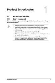
1.1.2 Motherboard layout Chapter 1 Refer to 1.1.9 Internal connectors and 2.3.1 Rear I/O connection for more information about rear panel connectors and internal connectors. 1-2 Chapter 1: Product Introduction
1.1.2 Motherboard layout Chapter 1 Refer to 1.1.9 Internal connectors and 2.3.1 Rear I/O connection for more information about rear panel connectors and internal connectors. 1-2 Chapter 1: Product Introduction

Users Manual English
Page 16
...8226; The product warranty does not cover damage to the PnP cap/socket contacts/motherboard components. Chapter 1 Ensure that the PnP cap is shipment/ transit-related. • Keep the cap after installing the motherboard. ASUS will shoulder the cost of repair only if the damage is on the socket ...and the socket contacts are unplugged before installing the CPU. • Upon purchase of the motherboard, ensure that you see any damage to the socket...
...8226; The product warranty does not cover damage to the PnP cap/socket contacts/motherboard components. Chapter 1 Ensure that the PnP cap is shipment/ transit-related. • Keep the cap after installing the motherboard. ASUS will shoulder the cost of repair only if the damage is on the socket ...and the socket contacts are unplugged before installing the CPU. • Upon purchase of the motherboard, ensure that you see any damage to the socket...

Users Manual English
Page 17
Chapter 1 1.1.4 System memory The motherboard comes with four DDR 4 (Double Data Rate 4) Dual Inline Memory Modules (DIMM) slots. A DDR4 module is notched differently from a DDR, DDR2 or DDR3 module. DO NOT install a DDR, DDR2 or DDR3 memory module to the DDR4 slot. Recommended memory configurations ASUS WS C246 PRO 1-5
Chapter 1 1.1.4 System memory The motherboard comes with four DDR 4 (Double Data Rate 4) Dual Inline Memory Modules (DIMM) slots. A DDR4 module is notched differently from a DDR, DDR2 or DDR3 module. DO NOT install a DDR, DDR2 or DDR3 memory module to the DDR4 slot. Recommended memory configurations ASUS WS C246 PRO 1-5

Users Manual English
Page 19
Chapter 1 Slot No. 1 2 3 4 5 6 Slot Description PCIE x1_1 slot PCIE x16_1 slot PCIE x1_2 slot PCIE x16_2 slot PCIE x16_3 slot PCIE x16_4 slot ASUS WS C246 PRO 1-7 1.1.5 Expansion slots Unplug the power cord before adding or removing expansion cards. Failure to do so may cause you physical injury and damage motherboard components.
Chapter 1 Slot No. 1 2 3 4 5 6 Slot Description PCIE x1_1 slot PCIE x16_1 slot PCIE x1_2 slot PCIE x16_2 slot PCIE x16_3 slot PCIE x16_4 slot ASUS WS C246 PRO 1-7 1.1.5 Expansion slots Unplug the power cord before adding or removing expansion cards. Failure to do so may cause you physical injury and damage motherboard components.

Users Manual English
Page 20
... sufficient power when running CrossFireX™ mode. • We recommend you connect the EATX12V_1 cable when running CrossFireX™. • Connect a chassis fan to the motherboard connector labeled CHA_FAN1/2 when using multiple graphics cards for better thermal environment. 1-8 Chapter 1: Product Introduction
... sufficient power when running CrossFireX™ mode. • We recommend you connect the EATX12V_1 cable when running CrossFireX™. • Connect a chassis fan to the motherboard connector labeled CHA_FAN1/2 when using multiple graphics cards for better thermal environment. 1-8 Chapter 1: Product Introduction

Users Manual English
Page 21
ASUS WS C246 PRO 1-9 The button also lights up the system. Power-on button The motherboard comes with a power-on a bare or open-case system. This is plugged to power up or wake up when the system is ideal for overclockers ... button that allows you to a power source indicating that you should shut down the system and unplug the power cable before removing or installing any motherboard component. 2.
ASUS WS C246 PRO 1-9 The button also lights up the system. Power-on button The motherboard comes with a power-on a bare or open-case system. This is plugged to power up or wake up when the system is ideal for overclockers ... button that allows you to a power source indicating that you should shut down the system and unplug the power cable before removing or installing any motherboard component. 2.

Users Manual English
Page 23
... a starting point for BIOS update. Q LED (CPU, DRAM, VGA, BOOT) Q LED checks key components (CPU, DRAM, VGA card, and booting devices) in sequence during motherboard booting process. ASUS WS C246 PRO 1-11 If an error is found, the corresponding LED remains lit until the problem is solved. This user-friendly design provides an intuitive way...
... a starting point for BIOS update. Q LED (CPU, DRAM, VGA, BOOT) Q LED checks key components (CPU, DRAM, VGA card, and booting devices) in sequence during motherboard booting process. ASUS WS C246 PRO 1-11 If an error is found, the corresponding LED remains lit until the problem is solved. This user-friendly design provides an intuitive way...

Users Manual English
Page 26
Front panel audio connector (10-1 pin AAFP) This connector is purchased separately. 1-14 Chapter 1: Product Introduction Connect one end of the motherboard's high-definition audio capability. 3. A TPM system also helps enhance network security, protect digital identities, and ensures platform integrity. Chapter 1 We recommend that supports HD Audio. ...
Front panel audio connector (10-1 pin AAFP) This connector is purchased separately. 1-14 Chapter 1: Product Introduction Connect one end of the motherboard's high-definition audio capability. 3. A TPM system also helps enhance network security, protect digital identities, and ensures platform integrity. Chapter 1 We recommend that supports HD Audio. ...

Users Manual English
Page 28
... USB 2.0 front or rear panel ports. Chapter 1 5. The 4-pin USB (Universal Serial Bus) Type-A port is for connecting USB 2.0 devices. Doing so will damage the motherboard! 6. Serial port connector (10-1 pin COM1) This connector is available for a serial (COM) port.
... USB 2.0 front or rear panel ports. Chapter 1 5. The 4-pin USB (Universal Serial Bus) Type-A port is for connecting USB 2.0 devices. Doing so will damage the motherboard! 6. Serial port connector (10-1 pin COM1) This connector is available for a serial (COM) port.

Users Manual English
Page 29
... connector. The S/PDIF module is for an additional Sony/Philips Digital Interface (S/PDIF) port. ASUS WS C246 PRO 1-17 Digital audio connector (4-1 pin SPDIF_OUT) This connector is purchased separately. These are not jumpers! Do not place jumper caps on the motherboard, ensuring that the CPU fan cable is securely installed to the CPU fan connector...
... connector. The S/PDIF module is for an additional Sony/Philips Digital Interface (S/PDIF) port. ASUS WS C246 PRO 1-17 Digital audio connector (4-1 pin SPDIF_OUT) This connector is purchased separately. These are not jumpers! Do not place jumper caps on the motherboard, ensuring that the CPU fan cable is securely installed to the CPU fan connector...

Users Manual English
Page 33
...all models. CPU installation • Ensure that the PnP cap is on the LGA1151 socket. • Upon purchase of the motherboard, ensure that you see any damage to the socket contacts resulting from incorrect CPU installation/removal, or misplacement/loss/incorrect removal ... The product warranty does not cover damage to the PnP cap/socket contacts/motherboard components. Load lever Chapter 2 Load plate ASUS WS C246 PRO Retention tab Gold triangle mark Alignment key CPU notches Alignment key 2-1 The motherboard layout may vary with models, but the installation steps are not bent....
...all models. CPU installation • Ensure that the PnP cap is on the LGA1151 socket. • Upon purchase of the motherboard, ensure that you see any damage to the socket contacts resulting from incorrect CPU installation/removal, or misplacement/loss/incorrect removal ... The product warranty does not cover damage to the PnP cap/socket contacts/motherboard components. Load lever Chapter 2 Load plate ASUS WS C246 PRO Retention tab Gold triangle mark Alignment key CPU notches Alignment key 2-1 The motherboard layout may vary with models, but the installation steps are not bent....

Users Manual English
Page 36
Install the ASUS Q-Shield to the chassis' rear I /O panel. 2. 2.1.3 Motherboard installation 1. Chapter 2 2-4 Chapter 2: Basic Installation Place the motherboard into the chassis, ensuring that its rear I/O ports are aligned to the chassis rear I /O panel.
Install the ASUS Q-Shield to the chassis' rear I /O panel. 2. 2.1.3 Motherboard installation 1. Chapter 2 2-4 Chapter 2: Basic Installation Place the motherboard into the chassis, ensuring that its rear I/O ports are aligned to the chassis rear I /O panel.
Users Manual English
Page 37
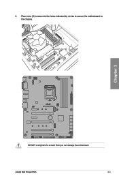
Chapter 2 DO NOT overtighten the screws! Doing so can damage the motherboard. ASUS WS C246 PRO 2-5 Place nine (9) screws into the holes indicated by circles to secure the motherboard to the chassis. 3.
Chapter 2 DO NOT overtighten the screws! Doing so can damage the motherboard. ASUS WS C246 PRO 2-5 Place nine (9) screws into the holes indicated by circles to secure the motherboard to the chassis. 3.


