
Users Manual English
Page 15
... as the power supply case, to avoid damaging them due to static electricity. • Hold components by the edges to the motherboard, peripherals, or components. ASUS TUF GAMING X570-PLUS 1-1 Chapter 1 Chapter 1: Product Introduction Product Introduction 1 1.1 Motherboard overview 1.1.1 Before you proceed Take note of the following precautions before you install motherboard components or change any...
... as the power supply case, to avoid damaging them due to static electricity. • Hold components by the edges to the motherboard, peripherals, or components. ASUS TUF GAMING X570-PLUS 1-1 Chapter 1 Chapter 1: Product Introduction Product Introduction 1 1.1 Motherboard overview 1.1.1 Before you proceed Take note of the following precautions before you install motherboard components or change any...

Users Manual English
Page 17
... 5. Addressable Gen 2 header (4-pin ADD_GEN2) 9. Front panel audio connector (10-1 pin AAFP) Page 1-15 1-14 1-10 1-4 1-17 1-4 1-8 1-18 1-12 1-16 1-11 1-9 1-13 1-12 1-15 1-10 ASUS TUF GAMING X570-PLUS 1-3 Chapter 1 Layout contents Connectors/Jumpers/Buttons and switches/Slots 1. M.2 Socket 3 11. Serial port connector (10-1 pin COM) 16. USB 2.0 connectors (10-1 pin USB78, USB910) 15...
... 5. Addressable Gen 2 header (4-pin ADD_GEN2) 9. Front panel audio connector (10-1 pin AAFP) Page 1-15 1-14 1-10 1-4 1-17 1-4 1-8 1-18 1-12 1-16 1-11 1-9 1-13 1-12 1-15 1-10 ASUS TUF GAMING X570-PLUS 1-3 Chapter 1 Layout contents Connectors/Jumpers/Buttons and switches/Slots 1. M.2 Socket 3 11. Serial port connector (10-1 pin COM) 16. USB 2.0 connectors (10-1 pin USB78, USB910) 15...

Users Manual English
Page 19
.... • This motherboard does not support DIMMs made up of 512 Mb (64 MB) chips or less (Memory chip capacity counts in Channel A and Channel B. ASUS TUF GAMING X570-PLUS 1-5 Chapter 1 Recommended memory configurations Memory configurations You may install 2 GB, 4 GB, 8 GB,16 GB, and s32 GB, unbuffered DDR4 DIMMs into the DIMM sockets. •...
.... • This motherboard does not support DIMMs made up of 512 Mb (64 MB) chips or less (Memory chip capacity counts in Channel A and Channel B. ASUS TUF GAMING X570-PLUS 1-5 Chapter 1 Recommended memory configurations Memory configurations You may install 2 GB, 4 GB, 8 GB,16 GB, and s32 GB, unbuffered DDR4 DIMMs into the DIMM sockets. •...

Users Manual English
Page 21
ASUS TUF GAMING X570-PLUS 1-7 Chapter 1 AMD Ryzen™ 3rd Generation Processors VGA Configuration Single VGA/PCIe card PCIe operating mode PCIe 4.0/3.0 x16_1 PCIe 4.0 x16_2 x16 N/A Dual VGA/PCIe card ...
ASUS TUF GAMING X570-PLUS 1-7 Chapter 1 AMD Ryzen™ 3rd Generation Processors VGA Configuration Single VGA/PCIe card PCIe operating mode PCIe 4.0/3.0 x16_1 PCIe 4.0 x16_2 x16 N/A Dual VGA/PCIe card ...

Users Manual English
Page 23
CLRTC PIN 1 TUF GAMING X570-PLUS Clear RTC RAM To erase the RTC RAM: 1. Use a metal object such as date, time, and system passwords. After clearing the CMOS, reinstall the battery. ... cord and turn ON the computer. 4. Hold down the key during the boot process and enter BIOS setup to clear the CMOS RTC RAM data. ASUS TUF GAMING X570-PLUS 1-9 If the steps above do not help, remove the onboard battery and short the two pins again to re-enter data. +3V_BAT GND Chapter 1 1.1.7 Jumpers...
CLRTC PIN 1 TUF GAMING X570-PLUS Clear RTC RAM To erase the RTC RAM: 1. Use a metal object such as date, time, and system passwords. After clearing the CMOS, reinstall the battery. ... cord and turn ON the computer. 4. Hold down the key during the boot process and enter BIOS setup to clear the CMOS RTC RAM data. ASUS TUF GAMING X570-PLUS 1-9 If the steps above do not help, remove the onboard battery and short the two pins again to re-enter data. +3V_BAT GND Chapter 1 1.1.7 Jumpers...
Users Manual English
Page 25
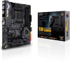
If you can create a RAID 0, RAID 1, and RAID 10 configuration through the onboard AMD X570 chipset. ASUS TUF GAMING X570-PLUS 1-11 AMD Serial ATA 6 Gb/s connectors (7-pin SATA6G_1-8) These connectors connect to section SATA Configuration for details. ...RSATA_TXP8 RSATA_TXN8 GND RSATA_RXN8 RSATA_RXP8 GND GND RSATA_RXP5 RSATA_RXN5 GND RSATA_TXN5 RSATA_TXP5 GND GND RSATA_RXP6 RSATA_RXN6 GND RSATA_TXN6 RSATA_TXP6 GND A SATA6G_5 SATA6G_6 B TUF GAMING X570-PLUS SATA 6 Gb/s connectors • These connectors are set the SATA Mode in the motherboard support DVD. • When using these...
If you can create a RAID 0, RAID 1, and RAID 10 configuration through the onboard AMD X570 chipset. ASUS TUF GAMING X570-PLUS 1-11 AMD Serial ATA 6 Gb/s connectors (7-pin SATA6G_1-8) These connectors connect to section SATA Configuration for details. ...RSATA_TXP8 RSATA_TXN8 GND RSATA_RXN8 RSATA_RXP8 GND GND RSATA_RXP5 RSATA_RXN5 GND RSATA_TXN5 RSATA_TXP5 GND GND RSATA_RXP6 RSATA_RXN6 GND RSATA_TXN6 RSATA_TXP6 GND A SATA6G_5 SATA6G_6 B TUF GAMING X570-PLUS SATA 6 Gb/s connectors • These connectors are set the SATA Mode in the motherboard support DVD. • When using these...
Users Manual English
Page 27
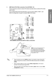
... mode. • Hard disk drive activity LED (2-pin HDD_LED) This 2-pin connector is for system reboot without turning off the system power. ASUS TUF GAMING X570-PLUS 1-13 PANEL +PWR_LED- Connect the chassis power LED cable to the HDD. • System warning speaker (4-pin SPEAKER) This 4-pin connector ...or soft-off button (2-pin PWRSW) This connector is read from or written to this connector. RESET +PWR_LED* Requires an ATX power supply TUF GAMING X570-PLUS System panel connector • System power LED (2-pin or 3-1 pin PLED) The 2-pin or 3-1 pin connector is for the system power ...
... mode. • Hard disk drive activity LED (2-pin HDD_LED) This 2-pin connector is for system reboot without turning off the system power. ASUS TUF GAMING X570-PLUS 1-13 PANEL +PWR_LED- Connect the chassis power LED cable to the HDD. • System warning speaker (4-pin SPEAKER) This 4-pin connector ...or soft-off button (2-pin PWRSW) This connector is read from or written to this connector. RESET +PWR_LED* Requires an ATX power supply TUF GAMING X570-PLUS System panel connector • System power LED (2-pin or 3-1 pin PLED) The 2-pin or 3-1 pin connector is for the system power ...
Users Manual English
Page 29
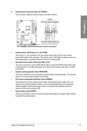
... 1 +5 Volts GND GND GND GND GND GND GND GND GND +5 Volts PSON# GND GND +3 Volts -12 Volts +3 Volts +3 Volts PIN 1 TUF GAMING X570-PLUS ATX power connectors • DO NOT connect the 4-pin power plug only, the motherboard may not boot up if the power is inadequate. • If.... The power supply plugs are for a serial (COM) port. Serial port connector (10-1 pin COM) This connector is purchased separately. ASUS TUF GAMING X570-PLUS 1-15 Find the proper orientation and push down firmly until the connectors completely fit. COM PIN 1 RXD DTR DSR CTS DCD TXD GND ...
... 1 +5 Volts GND GND GND GND GND GND GND GND GND +5 Volts PSON# GND GND +3 Volts -12 Volts +3 Volts +3 Volts PIN 1 TUF GAMING X570-PLUS ATX power connectors • DO NOT connect the 4-pin power plug only, the motherboard may not boot up if the power is inadequate. • If.... The power supply plugs are for a serial (COM) port. Serial port connector (10-1 pin COM) This connector is purchased separately. ASUS TUF GAMING X570-PLUS 1-15 Find the proper orientation and push down firmly until the connectors completely fit. COM PIN 1 RXD DTR DSR CTS DCD TXD GND ...
Users Manual English
Page 31
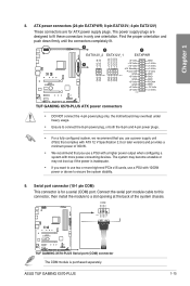
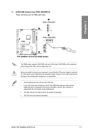
ASUS TUF GAMING X570-PLUS 1-17 Failure to do so may cause severe damage to the motherboard, peripherals, or components. • Actual lighting and color will vary with LED strip. &#... remove any component, ensure that the ATX power supply is switched off or the power cord is purchased separately. A RGB_HEADER1 B R A G +12V PIN 1 B RGB_HEADER2 PIN 1 +12V G R B B TUF GAMING X570-PLUS RGB Header The RGB header supports 5050 RGB multi-color LED strips (12V/G/R/B), with the 12V header on the motherboard. • The LED strip will...
ASUS TUF GAMING X570-PLUS 1-17 Failure to do so may cause severe damage to the motherboard, peripherals, or components. • Actual lighting and color will vary with LED strip. &#... remove any component, ensure that the ATX power supply is switched off or the power cord is purchased separately. A RGB_HEADER1 B R A G +12V PIN 1 B RGB_HEADER2 PIN 1 +12V G R B B TUF GAMING X570-PLUS RGB Header The RGB header supports 5050 RGB multi-color LED strips (12V/G/R/B), with the 12V header on the motherboard. • The LED strip will...

Users Manual English
Page 33
Chapter 2: Basic Installation Basic Installation 2.1 Building your PC system 2 2.1.1 The diagrams in this section are for all models. The motherboard layout may vary with models, but the installation steps are aligned to the chassis rear I /O panel. Motherboard installation 1. Place the motherboard into the chassis, ensuring that its rear I/O ports are the same for reference only. Install the ASUS I/O Shield to the chassis' rear I /O panel. 2. Chapter 2 ASUS TUF GAMING X570-PLUS 2-1
Chapter 2: Basic Installation Basic Installation 2.1 Building your PC system 2 2.1.1 The diagrams in this section are for all models. The motherboard layout may vary with models, but the installation steps are aligned to the chassis rear I /O panel. Motherboard installation 1. Place the motherboard into the chassis, ensuring that its rear I/O ports are the same for reference only. Install the ASUS I/O Shield to the chassis' rear I /O panel. 2. Chapter 2 ASUS TUF GAMING X570-PLUS 2-1
Users Manual English
Page 35
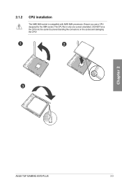
The CPU fits in only one correct orientation. Ensure you use a CPU designed for the AM4 socket. DO NOT force the CPU into the socket to prevent bending the connectors on the socket and damaging the CPU! 1 2 3 Chapter 2 ASUS TUF GAMING X570-PLUS 2-3 2.1.2 CPU installation The AMD AM4 socket is compatible with AMD AM4 processors.
The CPU fits in only one correct orientation. Ensure you use a CPU designed for the AM4 socket. DO NOT force the CPU into the socket to prevent bending the connectors on the socket and damaging the CPU! 1 2 3 Chapter 2 ASUS TUF GAMING X570-PLUS 2-3 2.1.2 CPU installation The AMD AM4 socket is compatible with AMD AM4 processors.

Users Manual English
Page 37
Type 2 1 2 3 When using this type of CPU fan, remove the screws and the retention module only. Chapter 2 ASUS TUF GAMING X570-PLUS 2-5 Do not remove the plate on the bottom.
Type 2 1 2 3 When using this type of CPU fan, remove the screws and the retention module only. Chapter 2 ASUS TUF GAMING X570-PLUS 2-5 Do not remove the plate on the bottom.

Users Manual English
Page 39
Chapter 2 2.1.5 ATX power connection A B OR Ensure to connect the 8-pin power plug. 2.1.6 SATA device connection OR OR ASUS TUF GAMING X570-PLUS 2-7
Chapter 2 2.1.5 ATX power connection A B OR Ensure to connect the 8-pin power plug. 2.1.6 SATA device connection OR OR ASUS TUF GAMING X570-PLUS 2-7

Users Manual English
Page 41
2.1.8 Expansion card installation To install PCIe x16 cards To install PCIe x1 cards Chapter 2 ASUS TUF GAMING X570-PLUS 2-9
2.1.8 Expansion card installation To install PCIe x16 cards To install PCIe x1 cards Chapter 2 ASUS TUF GAMING X570-PLUS 2-9

Users Manual English
Page 43
... controller. • We strongly recommend that you connect USB 3.2 Gen 2 devices to USB 3.2 Gen 2 ports for faster and better performance from your USB 3.2 Gen 2 devices. ASUS TUF GAMING X570-PLUS 2-11 DisplayPort 4. USB 3.2 Gen 2 (up to 5Gbps) ports 3. USB 3.2 Gen 1 (up to 10Gbps) ports 8. Optical S/PDIF Out port 7. LAN (RJ-45) port* 5. HDMI port 9. Audio...
... controller. • We strongly recommend that you connect USB 3.2 Gen 2 devices to USB 3.2 Gen 2 ports for faster and better performance from your USB 3.2 Gen 2 devices. ASUS TUF GAMING X570-PLUS 2-11 DisplayPort 4. USB 3.2 Gen 2 (up to 5Gbps) ports 3. USB 3.2 Gen 1 (up to 10Gbps) ports 8. Optical S/PDIF Out port 7. LAN (RJ-45) port* 5. HDMI port 9. Audio...
Users Manual English
Page 45
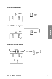
Connect to Stereo Speakers Connect to 2.1 channel Speakers Connect to 4.1 channel Speakers Chapter 2 ASUS TUF GAMING X570-PLUS 2-13
Connect to Stereo Speakers Connect to 2.1 channel Speakers Connect to 4.1 channel Speakers Chapter 2 ASUS TUF GAMING X570-PLUS 2-13

Users Manual English
Page 47
... One continuous beep followed by four short beeps Description VGA detected Quick boot set to the power connector at the back of the BIOS setting. ASUS TUF GAMING X570-PLUS 2-15 Chapter 2 2.3 Starting up for assistance. For systems with the last device on self tests (POST). Check the jumper settings and connections or call your...
... One continuous beep followed by four short beeps Description VGA detected Quick boot set to the power connector at the back of the BIOS setting. ASUS TUF GAMING X570-PLUS 2-15 Chapter 2 2.3 Starting up for assistance. For systems with the last device on self tests (POST). Check the jumper settings and connections or call your...

Users Manual English
Page 49
...to enable a more flexible and convenient mouse input. Chapter 3: BIOS Setup BIOS Setup 3.1 Knowing BIOS 3 The new ASUS UEFI BIOS is a Unified Extensible Interface that complies with UEFI architecture, offering a user-friendly interface that goes beyond the ..."UEFI BIOS" unless otherwise specified. BIOS (Basic Input and Output System) stores system hardware settings such as your operating system. Chapter 3 ASUS TUF GAMING X570-PLUS 3-1 DO NOT change the default BIOS settings except in this motherboard. • BIOS settings and options may result to ensure optimal performance...
...to enable a more flexible and convenient mouse input. Chapter 3: BIOS Setup BIOS Setup 3.1 Knowing BIOS 3 The new ASUS UEFI BIOS is a Unified Extensible Interface that complies with UEFI architecture, offering a user-friendly interface that goes beyond the ..."UEFI BIOS" unless otherwise specified. BIOS (Basic Input and Output System) stores system hardware settings such as your operating system. Chapter 3 ASUS TUF GAMING X570-PLUS 3-1 DO NOT change the default BIOS settings except in this motherboard. • BIOS settings and options may result to ensure optimal performance...

Users Manual English
Page 51
... you an overview of the BIOS setup program Turns the RGB LED lighting or functional LED on the devices you enter the BIOS setup program. ASUS TUF GAMING X570-PLUS 3-3 3.2.1 EZ Mode By default, the EZ Mode screen appears when you installed to the Setup Mode item in section Boot menu for details. To access...
... you an overview of the BIOS setup program Turns the RGB LED lighting or functional LED on the devices you enter the BIOS setup program. ASUS TUF GAMING X570-PLUS 3-3 3.2.1 EZ Mode By default, the EZ Mode screen appears when you installed to the Setup Mode item in section Boot menu for details. To access...

Users Manual English
Page 53
... button to select the language that you to search by BIOS item name, enter the item name to section 3.2.3 QFan Control for more information. Chapter 3 ASUS TUF GAMING X570-PLUS 3-5 Menu bar The menu bar on the menu bar displays the specific items for that the item has a submenu. Language This button above the menu...
... button to select the language that you to search by BIOS item name, enter the item name to section 3.2.3 QFan Control for more information. Chapter 3 ASUS TUF GAMING X570-PLUS 3-5 Menu bar The menu bar on the menu bar displays the specific items for that the item has a submenu. Language This button above the menu...


