User Manual
Page 3
......iii Notices...viii Safety information ix About this guide x Striker II Extreme / Striker II NSE specifications summary xii Chapter 1: Product introduction 1.1 Welcome 1-1 1.2 Package contents 1-1 1.3 Special features 1-2 1.3.1 Product highlights 1-2 1.3.2 ROG Intelligent Performance & Overclocking features... 1-4 1.3.3 ROG unique features 1-6 Chapter 2: Hardware information 2.1 Before you proceed 2-1 2.2 Motherboard overview 2-5 2.2.1 Placement direction 2-5 2.2.2 Screw holes 2-5 2.2.3 Motherboard layout 2-6 2.2.4 Audio card layout 2-6 2.2.5 Layout contents 2-7 2.3 Central...
......iii Notices...viii Safety information ix About this guide x Striker II Extreme / Striker II NSE specifications summary xii Chapter 1: Product introduction 1.1 Welcome 1-1 1.2 Package contents 1-1 1.3 Special features 1-2 1.3.1 Product highlights 1-2 1.3.2 ROG Intelligent Performance & Overclocking features... 1-4 1.3.3 ROG unique features 1-6 Chapter 2: Hardware information 2.1 Before you proceed 2-1 2.2 Motherboard overview 2-5 2.2.1 Placement direction 2-5 2.2.2 Screw holes 2-5 2.2.3 Motherboard layout 2-6 2.2.4 Audio card layout 2-6 2.2.5 Layout contents 2-7 2.3 Central...

User Manual
Page 13
... Calibration Intelligent overclocking tools: - one at midboard; CPU Level Up - O.C. Striker II Extreme / Striker II NSE specifications summary IEEE 1394 USB ROG Exclusive Overclocking features ROG Special Features Back Panel I /O Onboard Switches: Power / Reset / Clr CMOS (at rear panel) ASUS Q-Connector ASUS Q-Fan Plus ASUS EZ Flash 2 ASUS CrashFree BIOS ROG BIOS Wallpaper ASUS MyLogo 3™ 1 x PS/2 Keyboard (purple) 1 x S/PDIF Out (Coaxial + Optical...
... Calibration Intelligent overclocking tools: - one at midboard; CPU Level Up - O.C. Striker II Extreme / Striker II NSE specifications summary IEEE 1394 USB ROG Exclusive Overclocking features ROG Special Features Back Panel I /O Onboard Switches: Power / Reset / Clr CMOS (at rear panel) ASUS Q-Connector ASUS Q-Fan Plus ASUS EZ Flash 2 ASUS CrashFree BIOS ROG BIOS Wallpaper ASUS MyLogo 3™ 1 x PS/2 Keyboard (purple) 1 x S/PDIF Out (Coaxial + Optical...

User Manual
Page 14
Striker II Extreme / Striker II NSE specifications summary Internal I/O Connectors BIOS Features Manageability Accessories Software...Clr CMOS switch 1 x LCD Poster connector 1 x EL I/O shield connector 1 x System panel connector 1 x ROG connector 8 Mb Flash ROM, AWARD BIOS, PnP, DMI2.0, WfM2.0, ��S�M��B��IO...Cable ties User's manual The hottest DX10 game: Company of Heroes-Opposing Fronts Support DVD: Drivers ASUS PC Probe II ASUS Update ASUS AI Suite Futuremark® 3DMark® 06 Advanced Edition Kaspersky® Anti-virus software ATX Form...
Striker II Extreme / Striker II NSE specifications summary Internal I/O Connectors BIOS Features Manageability Accessories Software...Clr CMOS switch 1 x LCD Poster connector 1 x EL I/O shield connector 1 x System panel connector 1 x ROG connector 8 Mb Flash ROM, AWARD BIOS, PnP, DMI2.0, WfM2.0, ��S�M��B��IO...Cable ties User's manual The hottest DX10 game: Company of Heroes-Opposing Fronts Support DVD: Drivers ASUS PC Probe II ASUS Update ASUS AI Suite Futuremark® 3DMark® 06 Advanced Edition Kaspersky® Anti-virus software ATX Form...

User Manual
Page 17
... of the above items is damaged or missing, contact your motherboard package for buying an ASUS® Striker II Extreme / Striker II NSE motherboard! ROG Striker II Extreme / Striker II NSE 1-1 1.1 Welcome! Thank you start installing the motherboard, and hardware devices on it another standout in -1 ASUS Q-Connector Kit Cable ties DIY Pedestal Application DVD/CD ROG motherboard support DVD The hottest game: Company of Heroes-Opposing Fronts...
... of the above items is damaged or missing, contact your motherboard package for buying an ASUS® Striker II Extreme / Striker II NSE motherboard! ROG Striker II Extreme / Striker II NSE 1-1 1.1 Welcome! Thank you start installing the motherboard, and hardware devices on it another standout in -1 ASUS Q-Connector Kit Cable ties DIY Pedestal Application DVD/CD ROG motherboard support DVD The hottest game: Company of Heroes-Opposing Fronts...
User Manual
Page 19
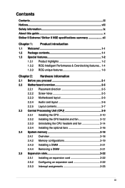
... page 2-24 for twice the current speed and bandwidth. PCIe 2.0 This motherboard supports the latest PCIe 2.0 device for details. Serial ATA 3.0 Gb/s technology and SATA-On-The-Go This motherboard supports the next-generation hard drives based on the Serial ATA (SATA) 3Gb...The motherboard supports DDR3 memory that simultaneously sends different audio streams to PCIe 1.0 devices. The dual-channel DDR3 architecture doubles the bandwidth of your system memory to meet the higher bandwidth requirements of data from WAN to your partners on your PC! ROG Striker II Extreme / Striker II NSE ...
... page 2-24 for twice the current speed and bandwidth. PCIe 2.0 This motherboard supports the latest PCIe 2.0 device for details. Serial ATA 3.0 Gb/s technology and SATA-On-The-Go This motherboard supports the next-generation hard drives based on the Serial ATA (SATA) 3Gb...The motherboard supports DDR3 memory that simultaneously sends different audio streams to PCIe 1.0 devices. The dual-channel DDR3 architecture doubles the bandwidth of your system memory to meet the higher bandwidth requirements of data from WAN to your partners on your PC! ROG Striker II Extreme / Striker II NSE ...

User Manual
Page 20
.../packaging to cooler temperatures and better efficiency. Overclocking is in line with the ASUS vision of Hazardous Substances (RoHS). This is never as easy as this motherboard ensures longer power component life spans and higher overclockability due to safeguard consumers'...ROG Intelligent Performance & Overclocking features Fusion Block System The Fusion Block System is the one phase solutions, this . No matter if you could have a more efficient thermal solution compared to Northbridge, Southbridge, Crosslinx, and even VRM with a single connection. Green ASUS This motherboard...
.../packaging to cooler temperatures and better efficiency. Overclocking is in line with the ASUS vision of Hazardous Substances (RoHS). This is never as easy as this motherboard ensures longer power component life spans and higher overclockability due to safeguard consumers'...ROG Intelligent Performance & Overclocking features Fusion Block System The Fusion Block System is the one phase solutions, this . No matter if you could have a more efficient thermal solution compared to Northbridge, Southbridge, Crosslinx, and even VRM with a single connection. Green ASUS This motherboard...

User Manual
Page 21
...an overheating GPU. Due to the chipset behavior, AC power off your system to overclocking failure, there is critical but risky. ASUS O.C. The Voltiminder LED allows quick voltage monitoring for each parameter. See page 5-33 for details. C.P.R. (CPU Parameter Recall)...of overheating. See pages 2-1 and 2-2 for details. Let the motherboard do the talking! See page 4-42 for maximum performance achievement. Frequency LED Worried that allows users to clear CMOS data. ROG Striker II Extreme / Striker II NSE 1-5 Acting as the "red zone" of extreme performance, overvoltage...
...an overheating GPU. Due to the chipset behavior, AC power off your system to overclocking failure, there is critical but risky. ASUS O.C. The Voltiminder LED allows quick voltage monitoring for each parameter. See page 5-33 for details. C.P.R. (CPU Parameter Recall)...of overheating. See pages 2-1 and 2-2 for details. Let the motherboard do the talking! See page 4-42 for maximum performance achievement. Frequency LED Worried that allows users to clear CMOS data. ROG Striker II Extreme / Striker II NSE 1-5 Acting as the "red zone" of extreme performance, overvoltage...

User Manual
Page 22
...monitor and tune the CPU power supply with AI Gear 3, this exclusive onboard switch allows gamers to effortlessly fine-tune the performance without having to the gamers of ROG. ASUS EPU The ASUS EPU utilizes innovative technology to find out what is running low intensity applications. External LCD ... flexible external display. Unlike other background noises then eliminates it in 3D environment during POST. See page 2-43 for details. SupremeFX II also provides a special tool to emphasize human voices in games to help make dialogues clearer. When system malfunction occurs, the LCD...
...monitor and tune the CPU power supply with AI Gear 3, this exclusive onboard switch allows gamers to effortlessly fine-tune the performance without having to the gamers of ROG. ASUS EPU The ASUS EPU utilizes innovative technology to find out what is running low intensity applications. External LCD ... flexible external display. Unlike other background noises then eliminates it in 3D environment during POST. See page 2-43 for details. SupremeFX II also provides a special tool to emphasize human voices in games to help make dialogues clearer. When system malfunction occurs, the LCD...

User Manual
Page 23
...dissipation for power saving during light loading. Optional Fan The optional fan is specifically designed to ensure quiet, cool, and efficient operation. ROG Striker II Extreme / Striker II NSE 1-7 AI Gear 3+ With a manual or automatic mode, AI Gear 3+ allows users to choose from four profiles to the OS environment..., dynamically overclocking the CPU speed in real time and lowering the voltage for the entire system. ASUS MyLogo 3 ASUS MyLogo 3 is a new feature present in light loading. The motherboard uses a special design on the printed circuit board (PCB) to 62% CPU power in the...
...dissipation for power saving during light loading. Optional Fan The optional fan is specifically designed to ensure quiet, cool, and efficient operation. ROG Striker II Extreme / Striker II NSE 1-7 AI Gear 3+ With a manual or automatic mode, AI Gear 3+ allows users to choose from four profiles to the OS environment..., dynamically overclocking the CPU speed in real time and lowering the voltage for the entire system. ASUS MyLogo 3 ASUS MyLogo 3 is a new feature present in light loading. The motherboard uses a special design on the printed circuit board (PCB) to 62% CPU power in the...
User Manual
Page 26
Chapter summary 2 2.1 Before you proceed 2-1 2.2 Motherboard overview 2-5 2.3 Central Processing Unit (CPU 2-9 2.4 System memory 2-18 2.5 Expansion slots 2-22 2.6 Slide switch 2-26 2.7 Aduio card, EL I/O shield, and LCD Poster Installation.......... 2-27 2.8 Connectors 2-29 ROG Striker II Extreme / Striker II NSE
Chapter summary 2 2.1 Before you proceed 2-1 2.2 Motherboard overview 2-5 2.3 Central Processing Unit (CPU 2-9 2.4 System memory 2-18 2.5 Expansion slots 2-22 2.6 Slide switch 2-26 2.7 Aduio card, EL I/O shield, and LCD Poster Installation.......... 2-27 2.8 Connectors 2-29 ROG Striker II Extreme / Striker II NSE

User Manual
Page 27
... in BIOS. Onboard LEDs The motherboard comes with the component. •...from the power supply. You may cause severe damage to the motherboard, peripherals, and/or components. There are also an LED ...you proceed Take note of the following precautions before you install motherboard components or change any motherboard settings. • Unplug the power cord from the wall ...of CPU, memory, northbridge, southbridge, and FSB frequency. CPU_CRAZY CPU_HIGH CPU_NORMAL STRIKER II EXTREME STRIKER II EXTREME/ STRIKER II NSE CPU LED CPU Voltage CPU PLL Voltage Normal (green) 1.10000~1.50000 1....
... in BIOS. Onboard LEDs The motherboard comes with the component. •...from the power supply. You may cause severe damage to the motherboard, peripherals, and/or components. There are also an LED ...you proceed Take note of the following precautions before you install motherboard components or change any motherboard settings. • Unplug the power cord from the wall ...of CPU, memory, northbridge, southbridge, and FSB frequency. CPU_CRAZY CPU_HIGH CPU_NORMAL STRIKER II EXTREME STRIKER II EXTREME/ STRIKER II NSE CPU LED CPU Voltage CPU PLL Voltage Normal (green) 1.10000~1.50000 1....

User Manual
Page 29
... (default), while five lit yellow LEDs shows that light up to the illustration below for the location of FSB frequency. FREQUENCY STRIKER II EXTREME STRIKER II EXTREME/ STRIKER II NSE Frequency LED CPU FSB 200MHz 200-299 300-399 400-499 500-599 600~ (Default) (Overclocking) (Overclocking) (Overclocking) ...Fast) CPU FSB 400MHz 400-450 451-499 500-549 550-599 600~ (Default) (Overclocking) (Overclocking) (Overclocking) (Overclocking) 1 2 3 4 5 (Default) (Fast) ROG Striker II Extreme / Striker II NSE 2-3 One lit yellow LED suggests that the frequency is high (fast).
... (default), while five lit yellow LEDs shows that light up to the illustration below for the location of FSB frequency. FREQUENCY STRIKER II EXTREME STRIKER II EXTREME/ STRIKER II NSE Frequency LED CPU FSB 200MHz 200-299 300-399 400-499 500-599 600~ (Default) (Overclocking) (Overclocking) (Overclocking) ...Fast) CPU FSB 400MHz 400-450 451-499 500-549 550-599 600~ (Default) (Overclocking) (Overclocking) (Overclocking) (Overclocking) 1 2 3 4 5 (Default) (Fast) ROG Striker II Extreme / Striker II NSE 2-3 One lit yellow LED suggests that the frequency is high (fast).
User Manual
Page 31
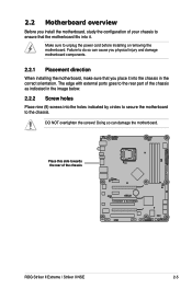
... image below. 2.2.2 Screw holes Place nine (9) screws into the holes indicated by circles to secure the motherboard to the chassis. DO NOT overtighten the screws! The edge with external ports goes to the rear part of the chassis STRIKER II EXTREME ROG Striker II Extreme / Striker II NSE 2-5 Failure to unplug the power cord before installing or removing the...
... image below. 2.2.2 Screw holes Place nine (9) screws into the holes indicated by circles to secure the motherboard to the chassis. DO NOT overtighten the screws! The edge with external ports goes to the rear part of the chassis STRIKER II EXTREME ROG Striker II Extreme / Striker II NSE 2-5 Failure to unplug the power cord before installing or removing the...
User Manual
Page 32
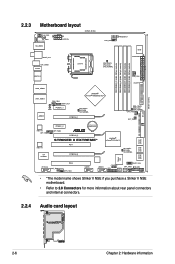
...174; 790i(Ultra) SLI™ CHA_FAN2 SPDIF_OUT ROG PCIEX1_1 NB_CRAZY NB_HIGH NB_NORMAL PCIEX16_1 DDR_CRAZY DDR_HIGH DDR_NORMAL OPT_FAN1 OPT_TEMP1 SATA1 SATA2 88E1116 OPT_TEMP2 88E1116 PCIEX1_2 Lithium Cell CMOS Power OPT_FAN2 PCIEX16_3 STRIKER II EXTREME* PCI1 VIA VT6308P PCIEX16_2 NVIDIA® nForce... USB910 CHASSIS ADH CLRTC_SW CHA_FAN3 RESET HD_LED PANEL • *The model name shows Striker II NSE if you purchase a Striker II NSE motherboard. • Refer to 2.8 Connectors for more information about rear panel connectors and internal connectors. 2.2.4 Audio card ...
...174; 790i(Ultra) SLI™ CHA_FAN2 SPDIF_OUT ROG PCIEX1_1 NB_CRAZY NB_HIGH NB_NORMAL PCIEX16_1 DDR_CRAZY DDR_HIGH DDR_NORMAL OPT_FAN1 OPT_TEMP1 SATA1 SATA2 88E1116 OPT_TEMP2 88E1116 PCIEX1_2 Lithium Cell CMOS Power OPT_FAN2 PCIEX16_3 STRIKER II EXTREME* PCI1 VIA VT6308P PCIEX16_2 NVIDIA® nForce... USB910 CHASSIS ADH CLRTC_SW CHA_FAN3 RESET HD_LED PANEL • *The model name shows Striker II NSE if you purchase a Striker II NSE motherboard. • Refer to 2.8 Connectors for more information about rear panel connectors and internal connectors. 2.2.4 Audio card ...

User Manual
Page 33
...2-24 2-24 Page 2-26 Page 2-29 2-29 2-29 2-29 2-30 2-30 2-30 2-30 2-30 2-30 2-30 2-30 2-31 2-31 2-31 2-31 ROG Striker II Extreme / Striker II NSE 2-7 Clear CMOS switch 15. DDR3 DIMM slots PCI slots PCI Express x 1 slots PCI Express x 16 slots Slide switch 1. LAN 2 (RJ-45) port 4.... USB 2.0 ports 5 and 6 *These audio ports are on the Supreme FX II audio card. Optical S/PDIF Out port 16. PS/2 keyboard port (purple) 2....
...2-24 2-24 Page 2-26 Page 2-29 2-29 2-29 2-29 2-30 2-30 2-30 2-30 2-30 2-30 2-30 2-30 2-31 2-31 2-31 2-31 ROG Striker II Extreme / Striker II NSE 2-7 Clear CMOS switch 15. DDR3 DIMM slots PCI slots PCI Express x 1 slots PCI Express x 16 slots Slide switch 1. LAN 2 (RJ-45) port 4.... USB 2.0 ports 5 and 6 *These audio ports are on the Supreme FX II audio card. Optical S/PDIF Out port 16. PS/2 keyboard port (purple) 2....

User Manual
Page 34
...) 5. IEEE 1394a port connector (10-1 pin IE1394_2) 6. ROG connector (2-pin ROG) 12. Floppy disk drive connector (34-1 pin FLOPPY) 4. Thermal sensor cable connectors (2-pin OPT_TEMP1/2/3) 7. Chassis intrusion connector (4-1 pin CHASSIS) 9. System panel connector (20-8 pin PANEL) Onboard switches 1. Digital audio connector (4-1 pin SPDIF_OUT, for ASUS HDMI VGA card) 10. IDE connector (40-1 pin...
...) 5. IEEE 1394a port connector (10-1 pin IE1394_2) 6. ROG connector (2-pin ROG) 12. Floppy disk drive connector (34-1 pin FLOPPY) 4. Thermal sensor cable connectors (2-pin OPT_TEMP1/2/3) 7. Chassis intrusion connector (4-1 pin CHASSIS) 9. System panel connector (20-8 pin PANEL) Onboard switches 1. Digital audio connector (4-1 pin SPDIF_OUT, for ASUS HDMI VGA card) 10. IDE connector (40-1 pin...
User Manual
Page 35
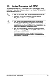
ROG Striker II Extreme / Striker II NSE 2-9 ASUS will process Return Merchandise Authorization (RMA) requests only if the motherboard comes with a surface mount LGA775 socket designed for the Intel® Core™2 Quad / Core™2...connect the chassis fan cable to the CHA_FAN1 connector to ensure system stability. • Upon purchase of the motherboard, make sure that all power cables are not bent. Contact your retailer immediately if the PnP cap is ...does not cover damage to the PnP cap/socket contacts/motherboard components. ASUS will shoulder the cost of the PnP cap.
ROG Striker II Extreme / Striker II NSE 2-9 ASUS will process Return Merchandise Authorization (RMA) requests only if the motherboard comes with a surface mount LGA775 socket designed for the Intel® Core™2 Quad / Core™2...connect the chassis fan cable to the CHA_FAN1 connector to ensure system stability. • Upon purchase of the motherboard, make sure that all power cables are not bent. Contact your retailer immediately if the PnP cap is ...does not cover damage to the PnP cap/socket contacts/motherboard components. ASUS will shoulder the cost of the PnP cap.
User Manual
Page 37
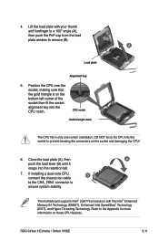
... the CPU notch. ROG Striker II Extreme / Striker II NSE 2-11 If installing a dual-core CPU, connect the chassis fan cable B to the CHA_FAN1 connector to the Appendix for more information on the socket and damaging the CPU! 6. DO NOT force the CPU into the socket to remove (B). B A Load plate Alignment key 5. The motherboard supports Intel®...
... the CPU notch. ROG Striker II Extreme / Striker II NSE 2-11 If installing a dual-core CPU, connect the chassis fan cable B to the CHA_FAN1 connector to the Appendix for more information on the socket and damaging the CPU! 6. DO NOT force the CPU into the socket to remove (B). B A Load plate Alignment key 5. The motherboard supports Intel®...
User Manual
Page 39
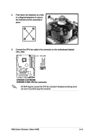
Hardware monitoring errors can occur if you fail to secure the heatsink and fan assembly in a diagonal sequence to plug this connector. ROG Striker II Extreme / Striker II NSE 2-13 2. Push down two fasteners at a time in B place. CPU_FAN GND CPU FAN PWR CPU FAN IN CPU FAN PWM STRIKER II EXTREME STRIKER II EXTREME/ STRIKER II NSE CPU fan connector DO NOT forget to the connector on the motherboard labeled CPU_FAN. Connect the CPU fan cable to connect the CPU fan connector! A A A B B B A 3.
Hardware monitoring errors can occur if you fail to secure the heatsink and fan assembly in a diagonal sequence to plug this connector. ROG Striker II Extreme / Striker II NSE 2-13 2. Push down two fasteners at a time in B place. CPU_FAN GND CPU FAN PWR CPU FAN IN CPU FAN PWM STRIKER II EXTREME STRIKER II EXTREME/ STRIKER II NSE CPU fan connector DO NOT forget to the connector on the motherboard labeled CPU_FAN. Connect the CPU fan cable to connect the CPU fan connector! A A A B B B A 3.

User Manual
Page 41
Rotate each fastener clockwise to the documentation in the boxed or stand-alone CPU fan package for emphasis.) Narrow end of the groove Refer to ensure correct orientation when reinstalling. The narrow end of the groove should point outward after resetting. (The photo shows the groove shaded for detailed information on CPU fan installation. 5. ROG Striker II Extreme / Striker II NSE 2-15
Rotate each fastener clockwise to the documentation in the boxed or stand-alone CPU fan package for emphasis.) Narrow end of the groove Refer to ensure correct orientation when reinstalling. The narrow end of the groove should point outward after resetting. (The photo shows the groove shaded for detailed information on CPU fan installation. 5. ROG Striker II Extreme / Striker II NSE 2-15


