SABERTOOTH 990FX R2.0 Diagram - Asus
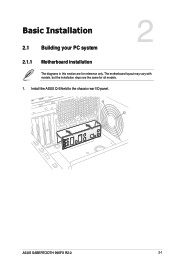
SABERTOOTH 990FX R2.0 Diagram
View Results Below
Free Asus SABERTOOTH 990FX R2.0 manuals!
Problems with Asus SABERTOOTH 990FX R2.0?
Ask a Question
Free Asus SABERTOOTH 990FX R2.0 manuals!
Problems with Asus SABERTOOTH 990FX R2.0?
Ask a Question
Related Manual Pages

Similar Questions

Reset Pin Connector Diagram
p4p800-vm/s asus motherboard i can not find reset pin connection. power on/off, hd led on motherboar...
p4p800-vm/s asus motherboard i can not find reset pin connection. power on/off, hd led on motherboar...
(Posted by srikalyaniprinterskaraikudi 10 years ago)

I Have Two Resistors Missing From My P6t Motherboard I Need A Circuit Diagram
(Posted by themacks30 13 years ago)