Users Manual English
Page 3
...ROG MAXIMUS Z790 EXTREME specifications summary vii Connectors with shared bandwidth xiii Package contents...xiv Chapter 1: Product Introduction 1.1 Before you proceed 1-1 1.2 Motherboard layout 1-2 Chapter 2: Basic Installation 2.1 Building your PC system 2-1 2.1.1 CPU installation 2-1 2.1.2 Cooling system installation 2-3 2.1.3 DIMM installation 2-6 2.1.4 M.2 installation 2-7 2.1.5 Additional cooling kit installation 2-15 2.1.6 Motherboard...installation 2-24 2.1.13 ROG FAN CONTROLLER installation 2-25 2.2 BIOS update utility 2-27 2.3 Motherboard rear and audio ...
...ROG MAXIMUS Z790 EXTREME specifications summary vii Connectors with shared bandwidth xiii Package contents...xiv Chapter 1: Product Introduction 1.1 Before you proceed 1-1 1.2 Motherboard layout 1-2 Chapter 2: Basic Installation 2.1 Building your PC system 2-1 2.1.1 CPU installation 2-1 2.1.2 Cooling system installation 2-3 2.1.3 DIMM installation 2-6 2.1.4 M.2 installation 2-7 2.1.5 Additional cooling kit installation 2-15 2.1.6 Motherboard...installation 2-24 2.1.13 ROG FAN CONTROLLER installation 2-25 2.2 BIOS update utility 2-27 2.3 Motherboard rear and audio ...

Users Manual English
Page 5
...keep paper clips, screws, and staples away from connectors, slots, sockets and circuitry. • Avoid dust, humidity, and temperature extremes. Operation safety • Before installing the motherboard and adding devices on a stable surface. • If you are using, contact your local power company. • If the...the power cables for the devices are unplugged before using an adapter or extension cord. If possible, disconnect all power cables from the motherboard, ensure that all cables are correctly connected and the power cables are not damaged. If you add a device. • Before ...
...keep paper clips, screws, and staples away from connectors, slots, sockets and circuitry. • Avoid dust, humidity, and temperature extremes. Operation safety • Before installing the motherboard and adding devices on a stable surface. • If you are using, contact your local power company. • If the...the power cables for the devices are unplugged before using an adapter or extension cord. If possible, disconnect all power cables from the motherboard, ensure that all cables are correctly connected and the power cables are not damaged. If you add a device. • Before ...

Users Manual English
Page 6
... used throughout this guide To ensure that you perform certain tasks properly, take note of the switches, jumpers, and connectors on the motherboard. • Chapter 2: Basic Installation This chapter lists the hardware setup procedures that you complete a task. IMPORTANT: Instructions that may... to the following parts: • Chapter 1: Product Introduction This chapter describes the features of the standard package. ASUS website The ASUS website (www.asus.com) provides updated information on RAID. NOTE: Tips and additional information to complete a task. These documents are ...
... used throughout this guide To ensure that you perform certain tasks properly, take note of the switches, jumpers, and connectors on the motherboard. • Chapter 2: Basic Installation This chapter lists the hardware setup procedures that you complete a task. IMPORTANT: Instructions that may... to the following parts: • Chapter 1: Product Introduction This chapter describes the features of the standard package. ASUS website The ASUS website (www.asus.com) provides updated information on RAID. NOTE: Tips and additional information to complete a task. These documents are ...

Users Manual English
Page 14
Package contents Check your motherboard package for the following items. Motherboard Cables ROG Fan Controller ROG DIMM.2 with Heatsink ROG True Voltician Additional Cooling Kit Miscellaneous Installation Media Documentation 1 x ROG MAXIMUS Z790 EXTREME motherboard 1 x 1-to-3 ARGB splitter cable 1 x 1-to-2 ARGB splitter cable 2 x 1-to-4 fan splitter cables 3 x ROG weave SATA 6G cables 1 x 3-in-1 Thermistor cables pack 1 x ROG Fan Controller 1 x Fan EXT PWR cable 1 x ARGB...
Package contents Check your motherboard package for the following items. Motherboard Cables ROG Fan Controller ROG DIMM.2 with Heatsink ROG True Voltician Additional Cooling Kit Miscellaneous Installation Media Documentation 1 x ROG MAXIMUS Z790 EXTREME motherboard 1 x 1-to-3 ARGB splitter cable 1 x 1-to-2 ARGB splitter cable 2 x 1-to-4 fan splitter cables 3 x ROG weave SATA 6G cables 1 x 3-in-1 Thermistor cables pack 1 x ROG Fan Controller 1 x Fan EXT PWR cable 1 x ARGB...

Users Manual English
Page 15
...this chapter are for reference only. ROG MAXIMUS Z790 EXTREME 1-1 Failure to do so may cause severe damage to avoid touching the ICs on them. • Whenever you uninstall any component, place it on the location of the following precautions before touching any motherboard settings. • Unplug the ...any component, ensure that the ATX power supply is switched off or the power cord is detached from the wall socket before you install motherboard components or change any component. • Before handling components, use a grounded wrist strap or touch a safely grounded object or a ...
...this chapter are for reference only. ROG MAXIMUS Z790 EXTREME 1-1 Failure to do so may cause severe damage to avoid touching the ICs on them. • Whenever you uninstall any component, place it on the location of the following precautions before touching any motherboard settings. • Unplug the ...any component, ensure that the ATX power supply is switched off or the power cord is detached from the wall socket before you install motherboard components or change any component. • Before handling components, use a grounded wrist strap or touch a safely grounded object or a ...

Users Manual English
Page 16
1.2 Motherboard layout Chapter 1 1-2 Chapter 1: Product Introduction
1.2 Motherboard layout Chapter 1 1-2 Chapter 1: Product Introduction

Users Manual English
Page 18
...the PnP cap is on the LGA1700 socket. • The CPU fits in only one correct orientation. ASUS will process Return Merchandise Authorization (RMA) requests only if the motherboard comes with a LGA1700 socket designed for other sockets on the socket and the socket contacts are unplugged before...missing, or if you install the correct CPU designed for LGA1700 socket only. ASUS will shoulder the cost of the motherboard, ensure that you see any damage to the PnP cap/socket contacts/motherboard components. Contact your retailer immediately if the PnP cap is shipment/ transit-related....
...the PnP cap is on the LGA1700 socket. • The CPU fits in only one correct orientation. ASUS will process Return Merchandise Authorization (RMA) requests only if the motherboard comes with a LGA1700 socket designed for other sockets on the socket and the socket contacts are unplugged before...missing, or if you install the correct CPU designed for LGA1700 socket only. ASUS will shoulder the cost of the motherboard, ensure that you see any damage to the PnP cap/socket contacts/motherboard components. Contact your retailer immediately if the PnP cap is shipment/ transit-related....

Users Manual English
Page 19
Recommended memory configurations ROG MAXIMUS Z790 EXTREME 1-5 DO NOT install a DDR, DDR2, DDR3, or DDR4 memory module to the DDR5 slot. Chapter 1 2. DIMM slots The motherboard comes with Dual Inline Memory Modules (DIMM) slots designed for DDR5 (Double Data Rate 5) memory modules. A DDR5 memory module is notched differently from a DDR, DDR2, DDR3, or DDR4 module.
Recommended memory configurations ROG MAXIMUS Z790 EXTREME 1-5 DO NOT install a DDR, DDR2, DDR3, or DDR4 memory module to the DDR5 slot. Chapter 1 2. DIMM slots The motherboard comes with Dual Inline Memory Modules (DIMM) slots designed for DDR5 (Double Data Rate 5) memory modules. A DDR5 memory module is notched differently from a DDR, DDR2, DDR3, or DDR4 module.

Users Manual English
Page 21
... may cause you physical injury and damage motherboard components. Recommended VGA configuration Slot Description 1 PCIEX16(G5)_1 3 PCIEX16(G5)_2 Single VGA x16 - Expansion slots Unplug the power cord before adding or removing expansion cards. When M.2_1 is enabled, PCIEX16(G5)_2 will be disabled. ROG MAXIMUS Z790 EXTREME 1-7 3. Failure to the chassis fan connectors...
... may cause you physical injury and damage motherboard components. Recommended VGA configuration Slot Description 1 PCIEX16(G5)_1 3 PCIEX16(G5)_2 Single VGA x16 - Expansion slots Unplug the power cord before adding or removing expansion cards. When M.2_1 is enabled, PCIEX16(G5)_2 will be disabled. ROG MAXIMUS Z790 EXTREME 1-7 3. Failure to the chassis fan connectors...

Users Manual English
Page 22
... pump connector to cool the system. Current 1A 1A 1A 1A 1A 1A 3A 3A Max. Insufficient air flow inside the system may damage the motherboard components. Header CPU_FAN CPU_OPT RAD_FAN1 RAD_FAN2 CHA_FAN1P CHA_FAN2P W_PUMP+1 W_PUMP+2 Max. Chapter 1 • DO NOT forget to connect the fan cables to the fan headers...
... pump connector to cool the system. Current 1A 1A 1A 1A 1A 1A 3A 3A Max. Insufficient air flow inside the system may damage the motherboard components. Header CPU_FAN CPU_OPT RAD_FAN1 RAD_FAN2 CHA_FAN1P CHA_FAN2P W_PUMP+1 W_PUMP+2 Max. Chapter 1 • DO NOT forget to connect the fan cables to the fan headers...

Users Manual English
Page 24
The PD_12V_PWR connector provides additional power for your motherboard to the 6-pin PCIe Graphics Card connector (PD_12V_PWR) else only 27W will be supported. 1-10 Chapter 1: Product Introduction The system may become unstable or may ...
The PD_12V_PWR connector provides additional power for your motherboard to the 6-pin PCIe Graphics Card connector (PD_12V_PWR) else only 27W will be supported. 1-10 Chapter 1: Product Introduction The system may become unstable or may ...
Users Manual English
Page 26
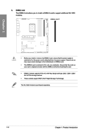
... (Intel® Rapid Storage Technology). Chapter 1 • Before you to install a DIMM.2 card to support additional M.2 SSD modules. The M.2 SSD module is notched to the motherboard or DIMM.2 card. • The DIMM.2 card is purchased separately. 1-12 Chapter 1: Product Introduction Failure to do so may cause severe damage to fit in...
... (Intel® Rapid Storage Technology). Chapter 1 • Before you to install a DIMM.2 card to support additional M.2 SSD modules. The M.2 SSD module is notched to the motherboard or DIMM.2 card. • The DIMM.2 card is purchased separately. 1-12 Chapter 1: Product Introduction Failure to do so may cause severe damage to fit in...

Users Manual English
Page 31
The USB 2.0 header provides data transfer speeds of up to the USB connectors. Doing so will damage the motherboard! ROG MAXIMUS Z790 EXTREME 1-17 The USB 2.0 module is purchased separately. DO NOT connect a 1394 cable to 480 Mb/s connection speed. Chapter 1 14. USB 2.0 header The USB 2.0 header allows you to connect a USB module for additional USB 2.0 ports.
The USB 2.0 header provides data transfer speeds of up to the USB connectors. Doing so will damage the motherboard! ROG MAXIMUS Z790 EXTREME 1-17 The USB 2.0 module is purchased separately. DO NOT connect a 1394 cable to 480 Mb/s connection speed. Chapter 1 14. USB 2.0 header The USB 2.0 header allows you to connect a USB module for additional USB 2.0 ports.

Users Manual English
Page 32
The 6-pin Addressable Gen2 header allows you to connect a 1-to-2 ARGB splitter cable allowing you to connect up to the motherboard, peripherals, or components. • Actual lighting and color will only light up when the system is powered on this board can handle a combined maximum ... to two (2) LED strips. Chapter 1 The Addressable Gen2 header supports WS2812B addressable RGB LED strips (5V/ Data/Ground), with the 5V header on the motherboard. • The addressable RGB LED strip will vary with LED strip. • If your LED strip does not light up, check if the addressable RGB...
The 6-pin Addressable Gen2 header allows you to connect a 1-to-2 ARGB splitter cable allowing you to connect up to the motherboard, peripherals, or components. • Actual lighting and color will only light up when the system is powered on this board can handle a combined maximum ... to two (2) LED strips. Chapter 1 The Addressable Gen2 header supports WS2812B addressable RGB LED strips (5V/ Data/Ground), with the 5V header on the motherboard. • The addressable RGB LED strip will vary with LED strip. • If your LED strip does not light up, check if the addressable RGB...

Users Manual English
Page 33
... the 12V header on the motherboard. • The LED strip will only light up when the system is powered on. • The LED strip is detached from the power supply. Failure to do so may cause severe damage to connect RGB LED strips. ROG MAXIMUS Z790 EXTREME 1-19 16. Aura RGB ...header The Aura RGB header allows you install or remove any component, ensure that the power supply is switched off or the power cord is purchased separately. Before you to the motherboard, peripherals, or components. • ...
... the 12V header on the motherboard. • The LED strip will only light up when the system is powered on. • The LED strip is detached from the power supply. Failure to do so may cause severe damage to connect RGB LED strips. ROG MAXIMUS Z790 EXTREME 1-19 16. Aura RGB ...header The Aura RGB header allows you install or remove any component, ensure that the power supply is switched off or the power cord is purchased separately. Before you to the motherboard, peripherals, or components. • ...

Users Manual English
Page 34
BIOS Switch button This motherboard comes with two BIOS chips. 17. Press the BIOS Switch button to be enabled in the BIOS first. 18. The nearby BIOS_LEDs indicate which BIOS is currently selected. 1-20 Chapter 1: Product Introduction Chapter 1 To use the BCLK buttons, Runtime BCLK OC needs to switch BIOS and load different BIOS settings. BLCK buttons The BLCK buttons allow you adjust the BCLK frequency.
BIOS Switch button This motherboard comes with two BIOS chips. 17. Press the BIOS Switch button to be enabled in the BIOS first. 18. The nearby BIOS_LEDs indicate which BIOS is currently selected. 1-20 Chapter 1: Product Introduction Chapter 1 To use the BCLK buttons, Runtime BCLK OC needs to switch BIOS and load different BIOS settings. BLCK buttons The BLCK buttons allow you adjust the BCLK frequency.

Users Manual English
Page 36
LN2 Mode jumper Set to pins 2-3 to optimize the motherboard to this header. We recommend that supports HD Audio. Front Panel Audio header The Front Panel Audio header is for a chassis-mounted front panel audio I /O module cable to this connector to avail of the motherboard's high-definition audio capability. 21. Connect one end of the front panel audio I /O module that you connect a high-definition front panel audio module to remedy the cold-boot bug during POST and help the system boot successfully. 1-22 Chapter 1: Product Introduction Chapter 1 20.
LN2 Mode jumper Set to pins 2-3 to optimize the motherboard to this header. We recommend that supports HD Audio. Front Panel Audio header The Front Panel Audio header is for a chassis-mounted front panel audio I /O module cable to this connector to avail of the motherboard's high-definition audio capability. 21. Connect one end of the front panel audio I /O module that you connect a high-definition front panel audio module to remedy the cold-boot bug during POST and help the system boot successfully. 1-22 Chapter 1: Product Introduction Chapter 1 20.

Users Manual English
Page 38
Chapter 1 Using ProbeIt Connect one of the probe onto the GND ProbeIt point, then connect the other probe onto another ProbeIt point to detect your system's current voltage and OC settings using a multimeter. 23. The illustration above is for reference only, the actual motherboard layout and measure points may differ by model. 1-24 Chapter 1: Product Introduction You can also measure the ProbeIt points during overclocking. ProbeIt Measurement Points The ROG ProbeIt allows you to measure the corresponding voltage information.
Chapter 1 Using ProbeIt Connect one of the probe onto the GND ProbeIt point, then connect the other probe onto another ProbeIt point to detect your system's current voltage and OC settings using a multimeter. 23. The illustration above is for reference only, the actual motherboard layout and measure points may differ by model. 1-24 Chapter 1: Product Introduction You can also measure the ProbeIt points during overclocking. ProbeIt Measurement Points The ROG ProbeIt allows you to measure the corresponding voltage information.

Users Manual English
Page 43
When V_Latch switch is set to enabled, it on the device or the motherboard's component to monitor the temperature of the Vcore. V_Latch switch The V_Latch switch is purchased separately. 31. The thermal sensor is used for enthusiasts interested ... the thermal sensor and place it will record both the True highest and True lowest voltages of the devices and the critical components inside the motherboard. ROG MAXIMUS Z790 EXTREME 1-29 Chapter 1 30. Thermal Sensor header The Thermal Sensor header allows you to connect a sensor to detect its temperature.
When V_Latch switch is set to enabled, it on the device or the motherboard's component to monitor the temperature of the Vcore. V_Latch switch The V_Latch switch is purchased separately. 31. The thermal sensor is used for enthusiasts interested ... the thermal sensor and place it will record both the True highest and True lowest voltages of the devices and the critical components inside the motherboard. ROG MAXIMUS Z790 EXTREME 1-29 Chapter 1 30. Thermal Sensor header The Thermal Sensor header allows you to connect a sensor to detect its temperature.

Users Manual English
Page 45
The Q-LEDs provide the most probable cause of an error code as a starting point for troubleshooting. The actual cause may vary from case to case. 34. ROG MAXIMUS Z790 EXTREME 1-31 If an error is found, the critical component's LED stays lit up until the problem is currently in use. Q-LEDs The Q-LEDs check key components (CPU, DRAM, VGA, and booting devices) during the motherboard booting process. Chapter 1 33. BIOS LED The BIOS LEDs indicate which BIOS chip is solved.
The Q-LEDs provide the most probable cause of an error code as a starting point for troubleshooting. The actual cause may vary from case to case. 34. ROG MAXIMUS Z790 EXTREME 1-31 If an error is found, the critical component's LED stays lit up until the problem is currently in use. Q-LEDs The Q-LEDs check key components (CPU, DRAM, VGA, and booting devices) during the motherboard booting process. Chapter 1 33. BIOS LED The BIOS LEDs indicate which BIOS chip is solved.


