User Guide
Page 14
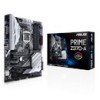
xiv Package contents Check your motherboard package for the following items. Motherboard Cables Accessories Application DVD Documentation 1 x ASUS PRIME Z370-A motherboard 3 x Serial ATA 6.0 Gb/s cables 1 x ASUS SLI HB BRIDGE (2-WAY-M) 1 x ASUS Q-Shield 1 x Q-Connector 1 x M.2 screw package 1 x CPU Installation Tool 1 x ASUS fan holder 1 x Motherboard support DVD 1 x User guide If any of the above items is damaged or missing, contact your retailer.
xiv Package contents Check your motherboard package for the following items. Motherboard Cables Accessories Application DVD Documentation 1 x ASUS PRIME Z370-A motherboard 3 x Serial ATA 6.0 Gb/s cables 1 x ASUS SLI HB BRIDGE (2-WAY-M) 1 x ASUS Q-Shield 1 x Q-Connector 1 x M.2 screw package 1 x CPU Installation Tool 1 x ASUS fan holder 1 x Motherboard support DVD 1 x User guide If any of the above items is damaged or missing, contact your retailer.
User Guide
Page 17
... as the power supply case, to avoid damaging them due to static electricity. • Hold components by the edges to the motherboard, peripherals, or components. ASUS PRIME Z370-A Series 1-1
... as the power supply case, to avoid damaging them due to static electricity. • Hold components by the edges to the motherboard, peripherals, or components. ASUS PRIME Z370-A Series 1-1
User Guide
Page 19
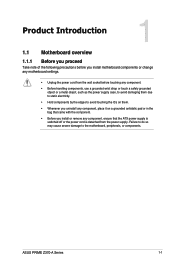
... RGB_HEADER) 17. Thermal sensor connector (2-pin T_SENSOR) Page 1-12 1-19 1-4 1-18 1-5 1-10 1-9 1-22 1-16 1-14 1-12 1-11 1-20 1-17 1-21 1-23 1-24 1-15 1-21 1-24 ASUS PRIME Z370-A Series 1-3 DDR4 DIMM slots 6. M.2_2(Socket 3)) 9. ATX power connectors (24-pin EATXPWR; 8-pin EATX12V) 3. Front panel audio connector (10-1 pin AAFP) 19. System panel connector...
... RGB_HEADER) 17. Thermal sensor connector (2-pin T_SENSOR) Page 1-12 1-19 1-4 1-18 1-5 1-10 1-9 1-22 1-16 1-14 1-12 1-11 1-20 1-17 1-21 1-23 1-24 1-15 1-21 1-24 ASUS PRIME Z370-A Series 1-3 DDR4 DIMM slots 6. M.2_2(Socket 3)) 9. ATX power connectors (24-pin EATXPWR; 8-pin EATX12V) 3. Front panel audio connector (10-1 pin AAFP) 19. System panel connector...
User Guide
Page 21
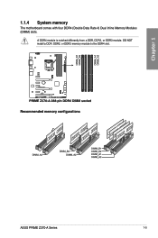
DO NOT install a DDR, DDR2, or DDR3 memory module to the DDR4 slot. A DDR4 module is notched differently from a DDR, DDR2, or DDR3 module. Recommended memory configurations ASUS PRIME Z370-A Series 1-5 Chapter 1 1.1.4 System memory The motherboard comes with four DDR4 (Double Data Rate 4) Dual Inline Memory Modules (DIMM) slots.
DO NOT install a DDR, DDR2, or DDR3 memory module to the DDR4 slot. A DDR4 module is notched differently from a DDR, DDR2, or DDR3 module. Recommended memory configurations ASUS PRIME Z370-A Series 1-5 Chapter 1 1.1.4 System memory The motherboard comes with four DDR4 (Double Data Rate 4) Dual Inline Memory Modules (DIMM) slots.
User Guide
Page 23
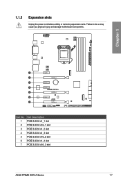
Chapter 1 Slot No. 1 2 3 4 5 6 7 Slot Description PCIE 3.0/2.0 x1_1 slot PCIE 3.0/2.0 x16_1 slot PCIE 3.0/2.0 x1_2 slot PCIE 3.0/2.0 x1_3 slot PCIE 3.0/2.0 x16_2 slot PCIE 3.0/2.0 x1_4 slot PCIE 3.0/2.0 x16_3 slot ASUS PRIME Z370-A Series 1-7 1.1.5 Expansion slots Unplug the power cord before adding or removing expansion cards. Failure to do so may cause you physical injury and damage motherboard components.
Chapter 1 Slot No. 1 2 3 4 5 6 7 Slot Description PCIE 3.0/2.0 x1_1 slot PCIE 3.0/2.0 x16_1 slot PCIE 3.0/2.0 x1_2 slot PCIE 3.0/2.0 x1_3 slot PCIE 3.0/2.0 x16_2 slot PCIE 3.0/2.0 x1_4 slot PCIE 3.0/2.0 x16_3 slot ASUS PRIME Z370-A Series 1-7 1.1.5 Expansion slots Unplug the power cord before adding or removing expansion cards. Failure to do so may cause you physical injury and damage motherboard components.
User Guide
Page 25
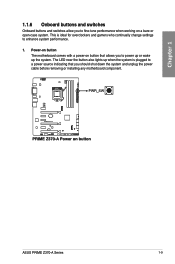
... installing any motherboard component. This is plugged to enhance system performance. 1. Power-on button The motherboard comes with a power-on a bare or open-case system. ASUS PRIME Z370-A Series 1-9 The LED near the button also lights up the system.
... installing any motherboard component. This is plugged to enhance system performance. 1. Power-on button The motherboard comes with a power-on a bare or open-case system. ASUS PRIME Z370-A Series 1-9 The LED near the button also lights up the system.

User Guide
Page 27
You can automatically reset parameter settings to default values. • Due to the chipset behavior, AC power off and turn on the CLRTC jumper. function. ASUS PRIME Z370-A Series 1-11 Short-circuit pin 1-2 with a metal object or jumper cap for about 5-10 seconds. 3. Placing a metal object or jumper cap will cause system boot ...
You can automatically reset parameter settings to default values. • Due to the chipset behavior, AC power off and turn on the CLRTC jumper. function. ASUS PRIME Z370-A Series 1-11 Short-circuit pin 1-2 with a metal object or jumper cap for about 5-10 seconds. 3. Placing a metal object or jumper cap will cause system boot ...
User Guide
Page 29
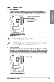
... LEDs provide the most probable cause of these key components during POST (Power-On Self-Test): CPU, memory modules, VGA card, and hard disk drives. ASUS PRIME Z370-A Series 1-13 The illustration below shows the location of the onboard LED.
... LEDs provide the most probable cause of these key components during POST (Power-On Self-Test): CPU, memory modules, VGA card, and hard disk drives. ASUS PRIME Z370-A Series 1-13 The illustration below shows the location of the onboard LED.

User Guide
Page 31
ASUS PRIME Z370-A Series 1-15 We recommend that supports HD Audio. Front panel audio connector (10-1 pin AAFP) This connector is for a chassis-mounted front panel audio I /O module cable to avail of the front panel audio I /O module that you connect a high-definition front panel audio module to this connector to this connector. Connect one end of the motherboard's high-definition audio capability. Chapter 1 2.
ASUS PRIME Z370-A Series 1-15 We recommend that supports HD Audio. Front panel audio connector (10-1 pin AAFP) This connector is for a chassis-mounted front panel audio I /O module cable to avail of the front panel audio I /O module that you connect a high-definition front panel audio module to this connector to this connector. Connect one end of the motherboard's high-definition audio capability. Chapter 1 2.
User Guide
Page 33
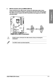
Connect the USB module cable to these connectors, then install the module to 480 Mb/s connection speed. ASUS PRIME Z370-A Series 1-17 This USB connector complies with USB 2.0 specification that supports up to a slot opening at the back of the system chassis. USB 2.0 connectors (10-1 pin USB910; DO NOT connect a 1394 cable to the USB connectors. Chapter 1 4. The USB 2.0 module is purchased separately. Doing so will damage the motherboard! USB1112) These connectors are for USB 2.0 ports.
Connect the USB module cable to these connectors, then install the module to 480 Mb/s connection speed. ASUS PRIME Z370-A Series 1-17 This USB connector complies with USB 2.0 specification that supports up to a slot opening at the back of the system chassis. USB 2.0 connectors (10-1 pin USB910; DO NOT connect a 1394 cable to the USB connectors. Chapter 1 4. The USB 2.0 module is purchased separately. Doing so will damage the motherboard! USB1112) These connectors are for USB 2.0 ports.
User Guide
Page 35
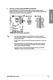
ATX power connectors (24-pin EATXPWR; 8-pin EATX12V) These connectors are designed to ensure the system stability. ASUS PRIME Z370-A Series 1-19 The system may become unstable or may not boot up if the power is inadequate. • If you want to use two or ...
ATX power connectors (24-pin EATXPWR; 8-pin EATX12V) These connectors are designed to ensure the system stability. ASUS PRIME Z370-A Series 1-19 The system may become unstable or may not boot up if the power is inadequate. • If you want to use two or ...

User Guide
Page 37
... up to six Thunderbolt-enabled devices and a DisplayPort-enabled display in a daisy-chain configuration. The add-on Thunderbolt I /O card and Thunderbolt cables are purchased separately. ASUS PRIME Z370-A Series 1-21
... up to six Thunderbolt-enabled devices and a DisplayPort-enabled display in a daisy-chain configuration. The add-on Thunderbolt I /O card and Thunderbolt cables are purchased separately. ASUS PRIME Z370-A Series 1-21
User Guide
Page 39
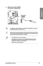
.... Before you install or remove any component, ensure that the ATX power supply is switched off or the power cord is for RGB LED strips. ASUS PRIME Z370-A Series 1-23 Chapter 1 11. Failure to do so may cause severe damage to the motherboard, peripherals, or components. • Actual lighting and color will vary...
.... Before you install or remove any component, ensure that the ATX power supply is switched off or the power cord is for RGB LED strips. ASUS PRIME Z370-A Series 1-23 Chapter 1 11. Failure to do so may cause severe damage to the motherboard, peripherals, or components. • Actual lighting and color will vary...

User Guide
Page 41
Chapter 2: Basic Installation Basic Installation 2.1 Building your PC system 2 2.1.1 The diagrams in this section are the same for all models. CPU installation Ensure that you install the correct CPU designed for LGA1155 and LGA1156 sockets on the LGA1151 socket. The motherboard layout may vary with models, but the installation steps are for reference only. Chapter 2 Top of CPU Bottom of CPU ASUS PRIME Z370-A Series Bottom of CPU 2-1 DO NOT install a CPU designed for LGA1151 socket only.
Chapter 2: Basic Installation Basic Installation 2.1 Building your PC system 2 2.1.1 The diagrams in this section are the same for all models. CPU installation Ensure that you install the correct CPU designed for LGA1155 and LGA1156 sockets on the LGA1151 socket. The motherboard layout may vary with models, but the installation steps are for reference only. Chapter 2 Top of CPU Bottom of CPU ASUS PRIME Z370-A Series Bottom of CPU 2-1 DO NOT install a CPU designed for LGA1151 socket only.
User Guide
Page 43
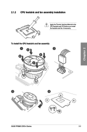
2.1.2 CPU heatsink and fan assembly installation Apply the Thermal Interface Material to the CPU heatsink and CPU before you install the heatsink and fan, if necessary. To install the CPU heatsink and fan assembly Chapter 2 ASUS PRIME Z370-A Series 2-3
2.1.2 CPU heatsink and fan assembly installation Apply the Thermal Interface Material to the CPU heatsink and CPU before you install the heatsink and fan, if necessary. To install the CPU heatsink and fan assembly Chapter 2 ASUS PRIME Z370-A Series 2-3
User Guide
Page 45
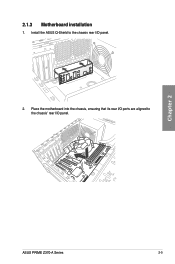
Chapter 2 ASUS PRIME Z370-A Series 2-5 2.1.3 Motherboard installation 1. Place the motherboard into the chassis, ensuring that its rear I/O ports are aligned to the chassis rear I /O panel. Install the ASUS Q-Shield to the chassis' rear I /O panel. 2.
Chapter 2 ASUS PRIME Z370-A Series 2-5 2.1.3 Motherboard installation 1. Place the motherboard into the chassis, ensuring that its rear I/O ports are aligned to the chassis rear I /O panel. Install the ASUS Q-Shield to the chassis' rear I /O panel. 2.
User Guide
Page 47
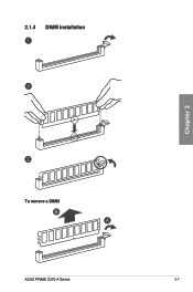
2.1.4 DIMM installation Chapter 2 To remove a DIMM ASUS PRIME Z370-A Series 2-7
2.1.4 DIMM installation Chapter 2 To remove a DIMM ASUS PRIME Z370-A Series 2-7
User Guide
Page 51
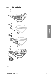
2.1.9 M.2 installation 1 2 3 Chapter 2 5 4 8 7 6 Supported M.2 type varies per motherboard. ASUS PRIME Z370-A Series 2-11
2.1.9 M.2 installation 1 2 3 Chapter 2 5 4 8 7 6 Supported M.2 type varies per motherboard. ASUS PRIME Z370-A Series 2-11
User Guide
Page 53
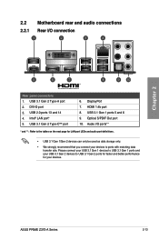
... audio port definitions. • USB 3.1 Gen 1/Gen 2 devices can only be used as data storage only. • We strongly recommend that you connect your devices. ASUS PRIME Z370-A Series 2-13 USB 2.0 ports 13 and 14 4. USB 3.1 Gen 2 Type-C™ port 6. Optical S/PDIF Out port 10. Intel® LAN port* 5. HDMI 1.4b port 8. Chapter...
... audio port definitions. • USB 3.1 Gen 1/Gen 2 devices can only be used as data storage only. • We strongly recommend that you connect your devices. ASUS PRIME Z370-A Series 2-13 USB 2.0 ports 13 and 14 4. USB 3.1 Gen 2 Type-C™ port 6. Optical S/PDIF Out port 10. Intel® LAN port* 5. HDMI 1.4b port 8. Chapter...

User Guide
Page 55
2.2.2 Audio I/O connections Audio I/O ports Connect to Headphone and Mic Connect to Stereo Speakers Chapter 2 Connect to 2 Speakers ASUS PRIME Z370-A Series 2-15
2.2.2 Audio I/O connections Audio I/O ports Connect to Headphone and Mic Connect to Stereo Speakers Chapter 2 Connect to 2 Speakers ASUS PRIME Z370-A Series 2-15


