

PR-DLS User Manual
Page 2
... translated into any means, except documentation kept by ASUS; ii ASUS ASSUMES NO RESPONSIBILITY OR LIABILITY FOR ANY ERRORS OR INACCURACIES THAT MAY APPEAR IN THIS MANUAL, INCLUDING THE PRODUCTS AND SOFTWARE DESCRIBED IN IT. SPECIFICATIONS AND INFORMATION CONTAINED IN THIS MANUAL ARE FURNISHED FOR... INFORMATIONAL USE ONLY, AND ARE SUBJECT TO CHANGE AT ANY TIME WITHOUT NOTICE, AND SHOULD NOT BE CONSTRUED AS A COMMITMENT BY ASUS. Checklist E1033 First Edition May 2002...
... translated into any means, except documentation kept by ASUS; ii ASUS ASSUMES NO RESPONSIBILITY OR LIABILITY FOR ANY ERRORS OR INACCURACIES THAT MAY APPEAR IN THIS MANUAL, INCLUDING THE PRODUCTS AND SOFTWARE DESCRIBED IN IT. SPECIFICATIONS AND INFORMATION CONTAINED IN THIS MANUAL ARE FURNISHED FOR... INFORMATIONAL USE ONLY, AND ARE SUBJECT TO CHANGE AT ANY TIME WITHOUT NOTICE, AND SHOULD NOT BE CONSTRUED AS A COMMITMENT BY ASUS. Checklist E1033 First Edition May 2002...

PR-DLS User Manual
Page 3
... Safety information vii About this guide viii How this guide is organized viii Conventions used in this guide ix Where to find more information ix ASUS contact information x PR-DLS specifications summary xi Chapter 1: Product introduction 1.1 Welcome 1-1 1.2 Package contents 1-1 1.3 Special features 1-2 1.3.1 Product highlights 1-2 1.3.2 Value-added solutions 1-4 1.4 Motherboard overview 1-6 1.4.1 Major components 1-6 1.4.2 Core...
... Safety information vii About this guide viii How this guide is organized viii Conventions used in this guide ix Where to find more information ix ASUS contact information x PR-DLS specifications summary xi Chapter 1: Product introduction 1.1 Welcome 1-1 1.2 Package contents 1-1 1.3 Special features 1-2 1.3.1 Product highlights 1-2 1.3.2 Value-added solutions 1-4 1.4 Motherboard overview 1-6 1.4.1 Major components 1-6 1.4.2 Core...

PR-DLS User Manual
Page 11
PR-DLS specifications summary CPU Chipsets Front Side Bus (FSB) Memory Onboard LAN Onboard SCSI Onboard VGA Expansion slots Rear panel I/O Internal connectors Support for Intel® Xeon&#...
PR-DLS specifications summary CPU Chipsets Front Side Bus (FSB) Memory Onboard LAN Onboard SCSI Onboard VGA Expansion slots Rear panel I/O Internal connectors Support for Intel® Xeon&#...

PR-DLS User Manual
Page 12
PR-DLS specifications summary BIOS features Form Factor Support CD contents 4Mb Flash ROM, Award BIOS with ACPI, DMI, Green, PnP features, and Enhanced Server BIOS features Extended ATX form factor: 12 in x 13 in (30.5 cm x 33 cm) Device drivers Management software Utilities Contact information * Specifications are subject to change without notice. xii
PR-DLS specifications summary BIOS features Form Factor Support CD contents 4Mb Flash ROM, Award BIOS with ACPI, DMI, Green, PnP features, and Enhanced Server BIOS features Extended ATX form factor: 12 in x 13 in (30.5 cm x 33 cm) Device drivers Management software Utilities Contact information * Specifications are subject to change without notice. xii

PR-DLS User Manual
Page 16
.... The PCI-X specification 1.0a allows full peer-to-peer transactions between PCI buses and provides options for intelligent I /O bandwidth for the next generation 64-bit PCI-X cards that support 133MHz bus. 1.3 Special features 1.3.1 Product highlights Latest processor technology The PR-DLS motherboard supports the Intel... deliver the required bandwidth for more information. DDR memory support Employing the Double Data Rate (DDR) memory technology, the PR-DLS motherboard supports up to 12GB of system memory using PC2100/1600 registered ECC DDR DIMMs. The ultra-fast 200MHz memory bus...
.... The PCI-X specification 1.0a allows full peer-to-peer transactions between PCI buses and provides options for intelligent I /O bandwidth for the next generation 64-bit PCI-X cards that support 133MHz bus. 1.3 Special features 1.3.1 Product highlights Latest processor technology The PR-DLS motherboard supports the Intel... deliver the required bandwidth for more information. DDR memory support Employing the Double Data Rate (DDR) memory technology, the PR-DLS motherboard supports up to 12GB of system memory using PC2100/1600 registered ECC DDR DIMMs. The ultra-fast 200MHz memory bus...
PR-DLS User Manual
Page 19
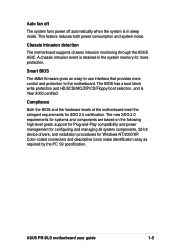
.... A chassis intrusion event is retained in sleep mode. Color-coded connectors and descriptive icons make identification easy as required by the PC '99 specification. ASUS PR-DLS motherboard user guide 1-5 Compliance Both the BIOS and the hardware levels of the motherboard meet the stringent requirements for SDG 2.0 certification. Auto fan off The ...
.... A chassis intrusion event is retained in sleep mode. Color-coded connectors and descriptive icons make identification easy as required by the PC '99 specification. ASUS PR-DLS motherboard user guide 1-5 Compliance Both the BIOS and the hardware levels of the motherboard meet the stringent requirements for SDG 2.0 certification. Auto fan off The ...

PR-DLS User Manual
Page 20
ASUS ASIC 14. ServerWorks® 64-bit I /O controller 20. Floppy disk connector 16. ServerWorks® Grand Champion LE North Bridge (CMIC-LE) 5. LSI® SCSI controller 12. PCI-X slots (PCI-X1 to Chapter 2 for the specifications of the PR-DLS motherboard as pointed ...and available features to facilitate the motherboard installation and future upgrades. A sufficient knowledge of the motherboard specifications will also help you install the PR-DLS motherboard, familiarize yourself with its components. 1.4.1 Major components The following are the major components of ...
ASUS ASIC 14. ServerWorks® 64-bit I /O controller 20. Floppy disk connector 16. ServerWorks® Grand Champion LE North Bridge (CMIC-LE) 5. LSI® SCSI controller 12. PCI-X slots (PCI-X1 to Chapter 2 for the specifications of the PR-DLS motherboard as pointed ...and available features to facilitate the motherboard installation and future upgrades. A sufficient knowledge of the motherboard specifications will also help you install the PR-DLS motherboard, familiarize yourself with its components. 1.4.1 Major components The following are the major components of ...

PR-DLS User Manual
Page 22
1.4.2 Core specifications 1 DDR DIMM sockets. The CMIC-LE device interfaces directly to the processor bus, and integrates the functions of the Grand Champion Low End (GCLE) SystemSet. A ... Champion LE north bridge (CMIC-LE). The processor interface supports a 400MHz Front Side Bus (FSB) providing a 3.2GB/s bandwidth, 2-way interleaved 3.2GB/s memory bandwidth with PCI 2.2 specification. These dual-channel bus master IDE connectors support up to 12GB registered ECC PC2100/1600 DDR DIMMs, and two high speed IMBs plus one thin...
1.4.2 Core specifications 1 DDR DIMM sockets. The CMIC-LE device interfaces directly to the processor bus, and integrates the functions of the Grand Champion Low End (GCLE) SystemSet. A ... Champion LE north bridge (CMIC-LE). The processor interface supports a 400MHz Front Side Bus (FSB) providing a 3.2GB/s bandwidth, 2-way interleaved 3.2GB/s memory bandwidth with PCI 2.2 specification. These dual-channel bus master IDE connectors support up to 12GB registered ECC PC2100/1600 DDR DIMMs, and two high speed IMBs plus one thin...

PR-DLS User Manual
Page 24
The controller provides a 32/64-bit, 33/66MHz interface to the PCI bus that supports PCI Specification Rev. 2.2, and to the PCI-X extension to the PCI Local Bus Rev 1.0a at clock rates of up to a Local Area Network (LAN) through a network ...
The controller provides a 32/64-bit, 33/66MHz interface to the PCI bus that supports PCI Specification Rev. 2.2, and to the PCI-X extension to the PCI Local Bus Rev 1.0a at clock rates of up to a Local Area Network (LAN) through a network ...

PR-DLS User Manual
Page 30
... socket) CPU Socket 2 (inner socket) 2-4 Chapter 2: Hardware information The processor includes the Intel® NetBurst™ micro-architecture that should match a specific corner of the CPU socket. Prestonia Gold Arrow PR-DLS PR-DLS Socket 604 Note in the 603-pin package with dual surface mount 604-pin Zero Insertion Force (ZIF) sockets. 2.4 Central Processing...
... socket) CPU Socket 2 (inner socket) 2-4 Chapter 2: Hardware information The processor includes the Intel® NetBurst™ micro-architecture that should match a specific corner of the CPU socket. Prestonia Gold Arrow PR-DLS PR-DLS Socket 604 Note in the 603-pin package with dual surface mount 604-pin Zero Insertion Force (ZIF) sockets. 2.4 Central Processing...
PR-DLS User Manual
Page 39
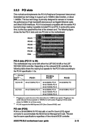
... in two cards reduces the bus speeds to increase the performance of the onboard SCSI controller. ASUS PR-DLS motherboard user guide 2-13 This slot has the same specifications regardless of high bandwidth devices such as Gigabit Ethernet cards and Ultra3 SCSI interfaces. 2.6.3 PCI slots... This motherboard implements the PCI-X (Peripheral Component Interconnect Extended) bus technology to support up to the PCI-X specification 1.0a. This bus technology is primarily designed for servers to 100MHz for the PCI-X slots according to 133MHz data transfers, or...
... in two cards reduces the bus speeds to increase the performance of the onboard SCSI controller. ASUS PR-DLS motherboard user guide 2-13 This slot has the same specifications regardless of high bandwidth devices such as Gigabit Ethernet cards and Ultra3 SCSI interfaces. 2.6.3 PCI slots... This motherboard implements the PCI-X (Peripheral Component Interconnect Extended) bus technology to support up to the PCI-X specification 1.0a. This bus technology is primarily designed for servers to 100MHz for the PCI-X slots according to 133MHz data transfers, or...
PR-DLS User Manual
Page 44
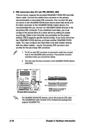
... to the secondary IDE connector. IDE connectors (two 40-1 pin PRI_IDE/SEC_IDE) This connector supports the provided UltraDMA/100/66 IDE hard disk ribbon cable. PR-DLS PR-DLS IDE Connectors Primary IDE Connector PIN 1 Secondary IDE Connector PIN 1 NOTE: Orient the red markings (usually zigzag) on the IDE ribbon cable to the UltraDMA... accordingly. You may configure two hard disks to the hard disk documentation for the primary IDE connector and another UltraDMA/100/66 cable. BIOS supports specific device bootup. Refer to be both master devices with two ribbon cables -
... to the secondary IDE connector. IDE connectors (two 40-1 pin PRI_IDE/SEC_IDE) This connector supports the provided UltraDMA/100/66 IDE hard disk ribbon cable. PR-DLS PR-DLS IDE Connectors Primary IDE Connector PIN 1 Secondary IDE Connector PIN 1 NOTE: Orient the red markings (usually zigzag) on the IDE ribbon cable to the UltraDMA... accordingly. You may configure two hard disks to the hard disk documentation for the primary IDE connector and another UltraDMA/100/66 cable. BIOS supports specific device bootup. Refer to be both master devices with two ribbon cables -
PR-DLS User Manual
Page 45
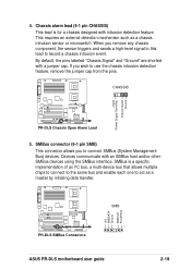
... a specific implementation of an I2C bus, a multi-device bus that allows multiple chips to connect to the same bus and enable each one to connect SMBus (System Management Bus) devices. CHASSIS +5Volt (Power Supply Stand By) Chassis Signal Ground PR-DLS PR-DLS Chassis Open Alarm Lead 5. PR-DLS PR-DLS SMBus Connectors +5V SMBDATA Ground SMBCLK FLOATING SMB 1 ASUS PR-DLS...
... a specific implementation of an I2C bus, a multi-device bus that allows multiple chips to connect to the same bus and enable each one to connect SMBus (System Management Bus) devices. CHASSIS +5Volt (Power Supply Stand By) Chassis Signal Ground PR-DLS PR-DLS Chassis Open Alarm Lead 5. PR-DLS PR-DLS SMBus Connectors +5V SMBDATA Ground SMBCLK FLOATING SMB 1 ASUS PR-DLS...

PR-DLS User Manual
Page 47
... inadequate, a USB header is available for additional USB ports. GND +12V Rotation GND +12V Rotation SYSFAN3 CPUFAN1 SYSFAN2 Rotation +12V GND PR-DLS PR-DLS 12-Volt Cooling Fan Power GND +12V Rotation CPUFAN2 SYSFAN1 GND +12V Rotation 8. USB header (10-1 pin USB2) If the USB ports... to the fan connectors. PR-DLS PR-DLS USB Header USB2 6 USB Power USBP3- Lack of 1A~2.22A (26.64W max.) at +12V. 7. The USB header complies with USB 1.1 specification that the black wire of each cable matches the ground pin of the connector. USBP2+ GND NC 5 ASUS PR-DLS motherboard user guide 2-21...
... inadequate, a USB header is available for additional USB ports. GND +12V Rotation GND +12V Rotation SYSFAN3 CPUFAN1 SYSFAN2 Rotation +12V GND PR-DLS PR-DLS 12-Volt Cooling Fan Power GND +12V Rotation CPUFAN2 SYSFAN1 GND +12V Rotation 8. USB header (10-1 pin USB2) If the USB ports... to the fan connectors. PR-DLS PR-DLS USB Header USB2 6 USB Power USBP3- Lack of 1A~2.22A (26.64W max.) at +12V. 7. The USB header complies with USB 1.1 specification that the black wire of each cable matches the ground pin of the connector. USBP2+ GND NC 5 ASUS PR-DLS motherboard user guide 2-21...

PR-DLS User Manual
Page 65
...appears. ASUS PR-DLS motherboard user guide 4-7 Sub-menu Note that you would within a sub-menu as shown on saving changes and exiting the setup program. Practice navigating through the entire help document. While moving around through the Setup program, note that will not fit in the Item Specific Help ... help window, it indicates that there is more information to the left of the fields, use the set default hot key to the Item Specific Help window, the BIOS setup program also provides a General Help screen. Saving changes and exiting the Setup program See "4.8 Exit Menu" for ...
...appears. ASUS PR-DLS motherboard user guide 4-7 Sub-menu Note that you would within a sub-menu as shown on saving changes and exiting the setup program. Practice navigating through the entire help document. While moving around through the Setup program, note that will not fit in the Item Specific Help ... help window, it indicates that there is more information to the left of the fields, use the set default hot key to the Item Specific Help window, the BIOS setup program also provides a General Help screen. Saving changes and exiting the Setup program See "4.8 Exit Menu" for ...

PR-DLS User Manual
Page 83
This feature requires an ATX power supply that provides at a certain time and day by selecting [By Date]. Configuration options: [Disabled] [Everyday] [By Date] ASUS PR-DLS motherboard user guide 4-25 You may configure your system to turn on the system. Configuration options: [Disabled] [Space Bar] [Ctrl-Esc] [Power Key] Automatic Power ... the day by selecting [Everyday] or at least 1A on the +5VSB lead. Power On By PS/2 Keyboard [Disabled] This parameter allows you to use specific keys on the keyboard to power up .
This feature requires an ATX power supply that provides at a certain time and day by selecting [By Date]. Configuration options: [Disabled] [Everyday] [By Date] ASUS PR-DLS motherboard user guide 4-25 You may configure your system to turn on the system. Configuration options: [Disabled] [Space Bar] [Ctrl-Esc] [Power Key] Automatic Power ... the day by selecting [Everyday] or at least 1A on the +5VSB lead. Power On By PS/2 Keyboard [Disabled] This parameter allows you to use specific keys on the keyboard to power up .
PR-DLS User Manual
Page 85
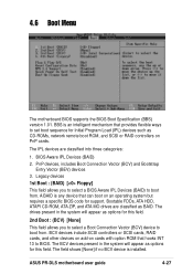
... intelligent mechanism that can boot on an operating system but requires a specific BIOS code for Initial Program Load (IPL) devices such as options for this field. A BAID is any device that provides flexible ways to boot from . BBS is installed. ASUS PR-DLS motherboard user guide 4-27 The BCV devices present in the system...
... intelligent mechanism that can boot on an operating system but requires a specific BIOS code for Initial Program Load (IPL) devices such as options for this field. A BAID is any device that provides flexible ways to boot from . BBS is installed. ASUS PR-DLS motherboard user guide 4-27 The BCV devices present in the system...
PR-DLS User Manual
Page 86
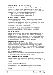
...Enabled] This field speeds up the Power-On-Self Test (POST) routine by the OS. If you wish to assign a device as options for a specific application, you must set that legacy device at the 1st Boot sequence. Configuration options: [No] [Yes] Reset Configuration Data [No] The Extended System... [Disabled] [Floppy] [HDD] [CD-ROM] [LAN Option ROM] [SCSI] Plug & Play O/S [No] This field allows you to enable or disable the MultiProcessor Specification 1.4 support. If you installed a nonPnP OS or if you want to prevent reassigning of how the system was configured the last time it was booted...
...Enabled] This field speeds up the Power-On-Self Test (POST) routine by the OS. If you wish to assign a device as options for a specific application, you must set that legacy device at the 1st Boot sequence. Configuration options: [No] [Yes] Reset Configuration Data [No] The Extended System... [Disabled] [Floppy] [HDD] [CD-ROM] [LAN Option ROM] [SCSI] Plug & Play O/S [No] This field allows you to enable or disable the MultiProcessor Specification 1.4 support. If you installed a nonPnP OS or if you want to prevent reassigning of how the system was configured the last time it was booted...

PR-DLS User Manual
Page 110
... install and use the SDMS NWPA SCSI Host Adapter Module (HAM) driver for NetWare. In addition, third party vendors are located on the ASUS Driver Support CD at: \Drivers\Sdms\Drivers\NetWare\ Copy all the drivers into a diskette and it "LSI driver for the NetWare system ...for NetWare". 5-18 Chapter 5: OS Installation For the LSI_U3.SYS driver, the executable file is provided for reference. 1. Use the manual to support their specific devices. In order to support SCSI devices, load the HAM in conjunction with a SCSI Custom Device Module (CDM). A. In the following, the NetWare ...
... install and use the SDMS NWPA SCSI Host Adapter Module (HAM) driver for NetWare. In addition, third party vendors are located on the ASUS Driver Support CD at: \Drivers\Sdms\Drivers\NetWare\ Copy all the drivers into a diskette and it "LSI driver for the NetWare system ...for NetWare". 5-18 Chapter 5: OS Installation For the LSI_U3.SYS driver, the executable file is provided for reference. 1. Use the manual to support their specific devices. In order to support SCSI devices, load the HAM in conjunction with a SCSI Custom Device Module (CDM). A. In the following, the NetWare ...