
User Manual
Page 4
... switches 1-35 1.12 Onboard LEDs 1-36 1.13 Software support 1-38 1.13.1 Installing an operating system 1-38 1.13.2 Support DVD information 1-38 Chapter 2 BIOS information 2.1 Managing and updating your BIOS 2-1 2.1.1 ASUS Update utility 2-1 2.1.2 ASUS EZ Flash 2 2-2 2.1.3 ASUS CrashFree BIOS 3 utility 2-3 2.1.4 ASUS BIOS Updater 2-4 2.2 BIOS setup... iGPU Max. Frequency [Auto 2-14 2.4.6 EPU Power Saving Mode [Disabled 2-15 2.4.7 OC Tuner 2-15 2.4.8 DRAM Timing Control 2-15 2.4.9 CPU Power Management 2-15 2.4.10 CPU Offset Mode Sign 2-16 2.4.11 iGPU Offset Mode Sign 2-16 iv
... switches 1-35 1.12 Onboard LEDs 1-36 1.13 Software support 1-38 1.13.1 Installing an operating system 1-38 1.13.2 Support DVD information 1-38 Chapter 2 BIOS information 2.1 Managing and updating your BIOS 2-1 2.1.1 ASUS Update utility 2-1 2.1.2 ASUS EZ Flash 2 2-2 2.1.3 ASUS CrashFree BIOS 3 utility 2-3 2.1.4 ASUS BIOS Updater 2-4 2.2 BIOS setup... iGPU Max. Frequency [Auto 2-14 2.4.6 EPU Power Saving Mode [Disabled 2-15 2.4.7 OC Tuner 2-15 2.4.8 DRAM Timing Control 2-15 2.4.9 CPU Power Management 2-15 2.4.10 CPU Offset Mode Sign 2-16 2.4.11 iGPU Offset Mode Sign 2-16 iv

User Manual
Page 23
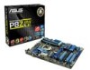
...CPU, Chassis and power fan connectors 2. (4-pin CPU_FAN, 4-pin CHA_FAN1/2, 1-32 11. DRAM LED 1-12 12 Clear RTC RAM (3-pin CLRTC) 1-26 1-17 . 13. Front panel audio connector (10-1 pin AAFP) 1-29 ASUS P8Z68-V LE 1-11 1.5.3 Motherboard layout 1 2 3 2 4 22.9cm(9.0in) KB_USB3_34 EPU CHA_FAN2 ... DDR3 DIMM_B2 (64bit, 240-pin module) EATXPWR 30.5cm(12.0in) LGA1155 USB3_12 MemOK! 6 DRAM_LED LAN1_USB12 AUDIO CHA_FAN1 PWR_FAN P8Z68-V LE AAFP PCIEX1_1 Lithium Cell CMOS Power ASM 1042 PCIEX16_1 1 USB3_34 7 ASM 1042 RTL 8111E Super I/O PCIEX1_2 TPU PCI1 PCIEX16_2 Intel...
...CPU, Chassis and power fan connectors 2. (4-pin CPU_FAN, 4-pin CHA_FAN1/2, 1-32 11. DRAM LED 1-12 12 Clear RTC RAM (3-pin CLRTC) 1-26 1-17 . 13. Front panel audio connector (10-1 pin AAFP) 1-29 ASUS P8Z68-V LE 1-11 1.5.3 Motherboard layout 1 2 3 2 4 22.9cm(9.0in) KB_USB3_34 EPU CHA_FAN2 ... DDR3 DIMM_B2 (64bit, 240-pin module) EATXPWR 30.5cm(12.0in) LGA1155 USB3_12 MemOK! 6 DRAM_LED LAN1_USB12 AUDIO CHA_FAN1 PWR_FAN P8Z68-V LE AAFP PCIEX1_1 Lithium Cell CMOS Power ASM 1042 PCIEX16_1 1 USB3_34 7 ASM 1042 RTL 8111E Super I/O PCIEX1_2 TPU PCI1 PCIEX16_2 Intel...

User Manual
Page 49
TPU LED The TPU LED lights when the TPU switch is turned to the error device will continue lighting until the problem is found , the LED next to Enable. 2. P8Z68-V LE DRAM LED P8Z68-V LE DRAM LED 2. If an error is solved. P8Z68-V LE P8Z68-V LE TPU LED ELED 730 ASUS P8Z68-V LE 1-37 DRAM LED DRAM LED checks the DRAM in sequence during motherboard booting process. This user-friendly design provides an intuitional way to locate the root problem within a second.
TPU LED The TPU LED lights when the TPU switch is turned to the error device will continue lighting until the problem is found , the LED next to Enable. 2. P8Z68-V LE DRAM LED P8Z68-V LE DRAM LED 2. If an error is solved. P8Z68-V LE P8Z68-V LE TPU LED ELED 730 ASUS P8Z68-V LE 1-37 DRAM LED DRAM LED checks the DRAM in sequence during motherboard booting process. This user-friendly design provides an intuitional way to locate the root problem within a second.


