
User Manual
Page 13
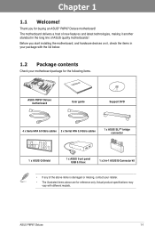
...Welcome! Thank you start installing the motherboard, and hardware devices on it another standout in -1 ASUS Q-Connector kit • If any of ASUS quality motherboards! ASUS P8P67 Deluxe 1-1 Actual product specifications may vary with the list below. 1.2 Package contents Check your motherboard package... for the following items. User Manual ASUS P8P67 Deluxe motherboard User guide Support DVD 4 x Serial ATA 6.0 Gb/s cables 2 x Serial ATA 3.0 Gb/s cables 1 x ASUS SLI™ bridge connector 1 x ASUS Q-Shield 1 x ASUS front panel USB 3.0 box 1 x 2-in the ...
...Welcome! Thank you start installing the motherboard, and hardware devices on it another standout in -1 ASUS Q-Connector kit • If any of ASUS quality motherboards! ASUS P8P67 Deluxe 1-1 Actual product specifications may vary with the list below. 1.2 Package contents Check your motherboard package... for the following items. User Manual ASUS P8P67 Deluxe motherboard User guide Support DVD 4 x Serial ATA 6.0 Gb/s cables 2 x Serial ATA 3.0 Gb/s cables 1 x ASUS SLI™ bridge connector 1 x ASUS Q-Shield 1 x ASUS front panel USB 3.0 box 1 x 2-in the ...

User Manual
Page 15
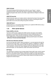
...range while performance reaches its full potential. All are accessible through a simple onboard switch or AI Suite II utility. ASUS P8P67 Deluxe 1-3 It also adjusts frequencies dynamically, cutting radiation interference by half to adjust CPU frequencies and ratios for fast, yet ... smart connectivity to ensure optimized performance, extreme system stability and greater power efficiency. Chapter 1 1.3.2 Dual Intelligent Processors 2 with ASUS' simple onboard switch or AI Suite II utility. The 16+2 digital architecture delivers twice the precision power, intelligently adjusting PWM ...
...range while performance reaches its full potential. All are accessible through a simple onboard switch or AI Suite II utility. ASUS P8P67 Deluxe 1-3 It also adjusts frequencies dynamically, cutting radiation interference by half to adjust CPU frequencies and ratios for fast, yet ... smart connectivity to ensure optimized performance, extreme system stability and greater power efficiency. Chapter 1 1.3.2 Dual Intelligent Processors 2 with ASUS' simple onboard switch or AI Suite II utility. The 16+2 digital architecture delivers twice the precision power, intelligently adjusting PWM ...
User Manual
Page 17
...cable is in regards to provide 5V power for the external SATA device. ASUS P8P67 Deluxe 1-5 Chapter 1 ASUS Q-Shield The specially designed ASUS Q-Shield does without the need of additional power source*. ASUS Q-Connector ASUS Q-Connector allows you to update the BIOS without using a bootable floppy disk...against Electronic Magnetic Interference (EMI). With better electric conductivity, it ideally protects your existing stereo speakers or headphones. ASUS EZ-Flash 2 ASUS EZ Flash 2 is European Union's Energy-related Products (ErP) ready, and ErP requires products to meet certain ...
...cable is in regards to provide 5V power for the external SATA device. ASUS P8P67 Deluxe 1-5 Chapter 1 ASUS Q-Shield The specially designed ASUS Q-Shield does without the need of additional power source*. ASUS Q-Connector ASUS Q-Connector allows you to update the BIOS without using a bootable floppy disk...against Electronic Magnetic Interference (EMI). With better electric conductivity, it ideally protects your existing stereo speakers or headphones. ASUS EZ-Flash 2 ASUS EZ Flash 2 is European Union's Energy-related Products (ErP) ready, and ErP requires products to meet certain ...

User Manual
Page 19
... as the power supply case, to avoid damaging them due to static electricity. • Hold components by the edges to the motherboard, peripherals, or components. ASUS P8P67 Deluxe 2-1 Failure to do so may cause severe damage to avoid touching the ICs on them. • Whenever you uninstall any component, place it on a grounded...
... as the power supply case, to avoid damaging them due to static electricity. • Hold components by the edges to the motherboard, peripherals, or components. ASUS P8P67 Deluxe 2-1 Failure to do so may cause severe damage to avoid touching the ICs on them. • Whenever you uninstall any component, place it on a grounded...

User Manual
Page 23
A DDR3 module is notched differently from a DDR or DDR2 module. 2.2.3 System memory The motherboard comes with four Double Data Rate 3 (DDR3) Dual Inline Memory Modules (DIMM) slots. DO NOT install a DDR or DDR2 memory module to the DDR3 slot. Recommended memory configurations Chapter 2 ASUS P8P67 Deluxe 2-5
A DDR3 module is notched differently from a DDR or DDR2 module. 2.2.3 System memory The motherboard comes with four Double Data Rate 3 (DDR3) Dual Inline Memory Modules (DIMM) slots. DO NOT install a DDR or DDR2 memory module to the DDR3 slot. Recommended memory configurations Chapter 2 ASUS P8P67 Deluxe 2-5

User Manual
Page 25
...; • • 1.65 • • • 1.65 • • 1.65 • • • 1.65 • • ASUS P8P67 Deluxe 2-7 Chip NO. G.SKILL F3-16000CL7T-6GBPS(XMP) 6GB(3 x 2GB) DS - - G.SKILL F3-16000CL7Q-8GBFLS(XMP) 8GB(4 x 2GB) DS - - GEIL GU34GB2000C9DC...8226; • • • • • • • • • • • • • P8P67 Deluxe Motherboard Qualified Vendors Lists (QVL) DDR3 1866(O.C.) MHz capability Vendor Part No. CORSAIR CMT6GX3M3A2000C8(XMP) 6GB ( 3x 2GB ) DS - - G.SKILL F3...
...; • • 1.65 • • • 1.65 • • 1.65 • • • 1.65 • • ASUS P8P67 Deluxe 2-7 Chip NO. G.SKILL F3-16000CL7T-6GBPS(XMP) 6GB(3 x 2GB) DS - - G.SKILL F3-16000CL7Q-8GBFLS(XMP) 8GB(4 x 2GB) DS - - GEIL GU34GB2000C9DC...8226; • • • • • • • • • • • • • P8P67 Deluxe Motherboard Qualified Vendors Lists (QVL) DDR3 1866(O.C.) MHz capability Vendor Part No. CORSAIR CMT6GX3M3A2000C8(XMP) 6GB ( 3x 2GB ) DS - - G.SKILL F3...

User Manual
Page 31
Chapter 2 1 2 3 ® 4 P8P67 DELUXE 5 6 7 RESET Slot No. Slot Description 1 PCIe 2.0 x1_1 slot 2 PCIe 2.0 x16_1 slot (single at x16 or dual at x8/x8 mode) 3 PCIe 2.0 x1_2 slot 4 PCI slot 1 5 ...) VGA configuration Single VGA/PCIe card Dual VGA/PCIe card PCI Express operating mode PCIe 2.0 x16_1 x16 (Recommend for single VGA) x8 PCIe 2.0 x16_2 N/A x8 ASUS P8P67 Deluxe 2-13 2.2.4 Expansion slots Ensure to do so may cause you physical injury and damage motherboard components. Failure to unplug the power cord before adding or...
Chapter 2 1 2 3 ® 4 P8P67 DELUXE 5 6 7 RESET Slot No. Slot Description 1 PCIe 2.0 x1_1 slot 2 PCIe 2.0 x16_1 slot (single at x16 or dual at x8/x8 mode) 3 PCIe 2.0 x1_2 slot 4 PCI slot 1 5 ...) VGA configuration Single VGA/PCIe card Dual VGA/PCIe card PCI Express operating mode PCIe 2.0 x16_1 x16 (Recommend for single VGA) x8 PCIe 2.0 x16_2 N/A x8 ASUS P8P67 Deluxe 2-13 2.2.4 Expansion slots Ensure to do so may cause you physical injury and damage motherboard components. Failure to unplug the power cord before adding or...

User Manual
Page 33
Reset switch Press the reset switch to fine-tune performance when working on a bare or opencase system. The switch also lights up the system. Chapter 2 ASUS P8P67 Deluxe 2-15 2.2.5 Onboard switches Onboard switches allow you should shut down the system and unplug the power cable before removing or plugging in any motherboard component. ...
Reset switch Press the reset switch to fine-tune performance when working on a bare or opencase system. The switch also lights up the system. Chapter 2 ASUS P8P67 Deluxe 2-15 2.2.5 Onboard switches Onboard switches allow you should shut down the system and unplug the power cable before removing or plugging in any motherboard component. ...

User Manual
Page 35
... the TurboV and Auto Tuning feature in the TurboV EVO application, adjust the BIOS setup program, or enable the TPU switch at the same time. ASUS P8P67 Deluxe 2-17 However, the system will be activated after the next system bootup. • You may use the last setting you change the switch setting to...
... the TurboV and Auto Tuning feature in the TurboV EVO application, adjust the BIOS setup program, or enable the TPU switch at the same time. ASUS P8P67 Deluxe 2-17 However, the system will be activated after the next system bootup. • You may use the last setting you change the switch setting to...

User Manual
Page 37
If an error is found , the LED next to the motherboard design. POST State LEDs The POST State LEDs of CPU, DRAM, VGA card, and HDD indicate key components status during POST (Power-on Self Test). ID LEDs The ID LEDs provide an elegant embellishment to the error device will continue lighting until the problem is solved. This user-friendly design provides an intuitional way to locate the root problem within a second. 2. Chapter 2 ASUS P8P67 Deluxe 2-19 2.2.6 Onboard LEDs 1.
If an error is found , the LED next to the motherboard design. POST State LEDs The POST State LEDs of CPU, DRAM, VGA card, and HDD indicate key components status during POST (Power-on Self Test). ID LEDs The ID LEDs provide an elegant embellishment to the error device will continue lighting until the problem is solved. This user-friendly design provides an intuitional way to locate the root problem within a second. 2. Chapter 2 ASUS P8P67 Deluxe 2-19 2.2.6 Onboard LEDs 1.

User Manual
Page 39
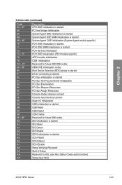
... LEDs The Q-Code LED design provides you the 2-digit display, allowing you to the Q-Code table below for ASL (see ASL Status Codes section below) ASUS P8P67 Deluxe 2-21
... LEDs The Q-Code LED design provides you the 2-digit display, allowing you to the Q-Code table below for ASL (see ASL Status Codes section below) ASUS P8P67 Deluxe 2-21
User Manual
Page 41
... started SCSI Reset SCSI Detect SCSI Enable Setup Verifying Password Start of Setup Reserved for ASL (see ASL Status Codes section below) Setup Input Wait ASUS P8P67 Deluxe 2-23
... started SCSI Reset SCSI Detect SCSI Enable Setup Verifying Password Start of Setup Reserved for ASL (see ASL Status Codes section below) Setup Input Wait ASUS P8P67 Deluxe 2-23
User Manual
Page 43
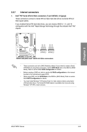
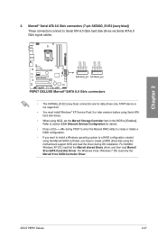
... Storage Technology through the onboard Intel® P67 chipset. • These connectors are using these connectors, set using Windows® XP SP3 or later versions. ASUS P8P67 Deluxe 2-25 Intel® P67 Serial ATA 6.0 Gb/s connectors (7-pin SATA6G_1/2 [gray]) These connectors connect to create a Serial ATA RAID set the SATA Mode item in...
... Storage Technology through the onboard Intel® P67 chipset. • These connectors are using these connectors, set using Windows® XP SP3 or later versions. ASUS P8P67 Deluxe 2-25 Intel® P67 Serial ATA 6.0 Gb/s connectors (7-pin SATA6G_1/2 [gray]) These connectors connect to create a Serial ATA RAID set the SATA Mode item in...
User Manual
Page 45
Chapter 2 3. ASUS P8P67 Deluxe 2-27 For 32/64bit Windows XP OS, load first the Marvell shared library driver, and then load Marvell 91xx SATA Controller Driver. For Windows Vista / ...
Chapter 2 3. ASUS P8P67 Deluxe 2-27 For 32/64bit Windows XP OS, load first the Marvell shared library driver, and then load Marvell 91xx SATA Controller Driver. For Windows Vista / ...

User Manual
Page 47
Digital audio connector (4-1 pin SPDIF_OUT) This connector is purchased separately. 7. Chapter 2 Never connect a USB cable to a slot opening at the back of the system chassis. ASUS P8P67 Deluxe 2-29 Connect the IEEE 1394a module cable to this connector, then install the module to a slot opening at the back of the system chassis. The ...
Digital audio connector (4-1 pin SPDIF_OUT) This connector is purchased separately. 7. Chapter 2 Never connect a USB cable to a slot opening at the back of the system chassis. ASUS P8P67 Deluxe 2-29 Connect the IEEE 1394a module cable to this connector, then install the module to a slot opening at the back of the system chassis. The ...

User Manual
Page 49
...;d�u�l�e��to��t�h�i�s�c��o�n�n�e��c�to [AC97]. Connect one orientation. ASUS P8P67 Deluxe 2-31 Find the proper orientation and push down firmly until the connectors completely fit. if you connect a high-definition front panel audio module to this...
...;d�u�l�e��to��t�h�i�s�c��o�n�n�e��c�to [AC97]. Connect one orientation. ASUS P8P67 Deluxe 2-31 Find the proper orientation and push down firmly until the connectors completely fit. if you connect a high-definition front panel audio module to this...

User Manual
Page 51
... blinks when the system is in sleep mode. • Hard disk drive activity LED (2-pin IDE_LED) This 2-pin connector is for the system power button. ASUS P8P67 Deluxe 2-33 Connect the chassis power LED cable to this connector. Connect the HDD Activity LED cable to this connector. The IDE LED lights up when...
... blinks when the system is in sleep mode. • Hard disk drive activity LED (2-pin IDE_LED) This 2-pin connector is for the system power button. ASUS P8P67 Deluxe 2-33 Connect the chassis power LED cable to this connector. Connect the HDD Activity LED cable to this connector. The IDE LED lights up when...

User Manual
Page 53
DO NOT install a LGA1156 CPU on the LGA1155 socket. 1 A B 2 3 ASUS P8P67 Deluxe 2-35 Chapter 2 2.3.2 CPU installation The LGA1156 CPU is incompatible with the LGA1155 socket.
DO NOT install a LGA1156 CPU on the LGA1155 socket. 1 A B 2 3 ASUS P8P67 Deluxe 2-35 Chapter 2 2.3.2 CPU installation The LGA1156 CPU is incompatible with the LGA1155 socket.

User Manual
Page 55
Chapter 2 2.3.3 CPU heatsink and fan assembly installation Apply the Thermal Interface Material to the CPU heatsink and CPU before you install the heatsink and fan if necessary. To install the CPU heatsink and fan assembly 1 A B 2 B A 3 4 ASUS P8P67 Deluxe 2-37
Chapter 2 2.3.3 CPU heatsink and fan assembly installation Apply the Thermal Interface Material to the CPU heatsink and CPU before you install the heatsink and fan if necessary. To install the CPU heatsink and fan assembly 1 A B 2 B A 3 4 ASUS P8P67 Deluxe 2-37

User Manual
Page 57
2.3.4 1 DIMM installation 2 Chapter 2 3 To remove a DIMM B A ASUS P8P67 Deluxe 2-39
2.3.4 1 DIMM installation 2 Chapter 2 3 To remove a DIMM B A ASUS P8P67 Deluxe 2-39


