
User Manual
Page 1
Motherboard P8H61-I LX E6873_P8H61-I LX.indb 1 2/15/12 6:36:49 PM
Motherboard P8H61-I LX E6873_P8H61-I LX.indb 1 2/15/12 6:36:49 PM
User Manual
Page 3
Contents Safety information vi About this guide vi P8H61-I LX specifications summary viii Chapter 1: Product introduction 1.1 Before you proceed 1-1 1.2 Motherboard overview 1-2 1.2.1 Placement direction 1-2 1.2.2 Screw holes 1-2 1.2.3 Motherboard layout 1-3 1.2.4 Layout contents 1-3 1.3 Central Processing Unit (CPU 1-4 1.3.1 Installing the CPU 1-4 1.3.2 Installing the CPU heatsink and fan 1-7 1.3.3 ... Internal connectors 1-17 1.8 Software support 1-22 1.8.1 Installing an operating system 1-22 1.8.2 Support DVD information 1-22 E6873_P8H61-I LX.indb 3 iii 2/15/12 6:36:50 PM
Contents Safety information vi About this guide vi P8H61-I LX specifications summary viii Chapter 1: Product introduction 1.1 Before you proceed 1-1 1.2 Motherboard overview 1-2 1.2.1 Placement direction 1-2 1.2.2 Screw holes 1-2 1.2.3 Motherboard layout 1-3 1.2.4 Layout contents 1-3 1.3 Central Processing Unit (CPU 1-4 1.3.1 Installing the CPU 1-4 1.3.2 Installing the CPU heatsink and fan 1-7 1.3.3 ... Internal connectors 1-17 1.8 Software support 1-22 1.8.1 Installing an operating system 1-22 1.8.2 Support DVD information 1-22 E6873_P8H61-I LX.indb 3 iii 2/15/12 6:36:50 PM

User Manual
Page 6
...following parts: • Chapter 1: Product introduction This chapter describes the features of the motherboard and the new technology it may become wet. • Place the product on it by yourself. vi E6873_P8H61-I LX.indb 6 2/15/12 6:36:51 PM Do not place the product in your... dealer immediately. • To avoid short circuits, keep paper clips, screws, and staples away from the motherboard, ensure that all power cables are unplugged. •...
...following parts: • Chapter 1: Product introduction This chapter describes the features of the motherboard and the new technology it may become wet. • Place the product on it by yourself. vi E6873_P8H61-I LX.indb 6 2/15/12 6:36:51 PM Do not place the product in your... dealer immediately. • To avoid short circuits, keep paper clips, screws, and staples away from the motherboard, ensure that all power cables are unplugged. •...

User Manual
Page 11
... shut down the system and unplug the power cable before you install motherboard components or change any motherboard settings. • Unplug the power cord from the power supply. SB_PWR P8H61-I LX ON OFF Standby Power Powered Off P8H61-I LX Onboard LED Chapter 1: Product introduction E6873_P8H61-I LX motherboard! This is a reminder that the ATX power supply is damaged or..., such as the power supply case, to avoid damaging them due to static electricity. • Hold components by the edges to page x for buying an ASUS® P8H61-I LX.indb 1 1-1 2/15/12 6:36:55 PM
... shut down the system and unplug the power cable before you install motherboard components or change any motherboard settings. • Unplug the power cord from the power supply. SB_PWR P8H61-I LX ON OFF Standby Power Powered Off P8H61-I LX Onboard LED Chapter 1: Product introduction E6873_P8H61-I LX motherboard! This is a reminder that the ATX power supply is damaged or..., such as the power supply case, to avoid damaging them due to static electricity. • Hold components by the edges to page x for buying an ASUS® P8H61-I LX.indb 1 1-1 2/15/12 6:36:55 PM

User Manual
Page 12
... the configuration of the chassis P8H61-I LX 1-2 E6873_P8H61-I LX.indb 2 ASUS P8H61-I LX 2/15/12 6:36:57 PM Place this side towards the rear of your chassis to ensure that the motherboard fits into the chassis in the correct orientation. The edge with external ports goes to the...Place four screws into the holes indicated by circles to secure the motherboard to do so can damage the motherboard. Doing so can cause you physical injury and damage motherboard components. 1.2.1 Placement direction When installing the motherboard, ensure that you place it into it. Failure to the ...
... the configuration of the chassis P8H61-I LX 1-2 E6873_P8H61-I LX.indb 2 ASUS P8H61-I LX 2/15/12 6:36:57 PM Place this side towards the rear of your chassis to ensure that the motherboard fits into the chassis in the correct orientation. The edge with external ports goes to the...Place four screws into the holes indicated by circles to secure the motherboard to do so can damage the motherboard. Doing so can cause you physical injury and damage motherboard components. 1.2.1 Placement direction When installing the motherboard, ensure that you place it into it. Failure to the ...
User Manual
Page 13
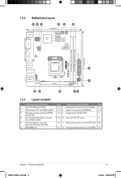
... audio connector (4-1 pin SPDIF_OUT) 1-20 1-9 12 Front panel audio connector (10-1 pin AAFP) 1-17 Chapter 1: Product introduction E6873_P8H61-I LX DDR3 DIMMA1 (64bit, 240-pin module) DDR3 DIMMB1 (64bit, 240-pin module) VGA CLRTC RTL 8111E USB34 LAN1_USB12 AUDIO AAFP VIA VT1708S...SATA3G_1/2/3/4) 5. Clear RTC RAM (3-pin CLRTC) 2. 1.2.3 Motherboard layout 123 45 6 17cm(6.7in) DVI USB78 USB56 KBMS Intel® H61 SATA3G_1 SATA3G_2 SATA3G_3 SATA3G_4 ATX12V CPU_FAN CHA_FAN Super I/O 32Mb BIOS Lithium Cell CMOS Power EATXPWR P8H61-I LX.indb 3 1-3 2/15/12 6:36:58 PM CPU...
... audio connector (4-1 pin SPDIF_OUT) 1-20 1-9 12 Front panel audio connector (10-1 pin AAFP) 1-17 Chapter 1: Product introduction E6873_P8H61-I LX DDR3 DIMMA1 (64bit, 240-pin module) DDR3 DIMMB1 (64bit, 240-pin module) VGA CLRTC RTL 8111E USB34 LAN1_USB12 AUDIO AAFP VIA VT1708S...SATA3G_1/2/3/4) 5. Clear RTC RAM (3-pin CLRTC) 2. 1.2.3 Motherboard layout 123 45 6 17cm(6.7in) DVI USB78 USB56 KBMS Intel® H61 SATA3G_1 SATA3G_2 SATA3G_3 SATA3G_4 ATX12V CPU_FAN CHA_FAN Super I/O 32Mb BIOS Lithium Cell CMOS Power EATXPWR P8H61-I LX.indb 3 1-3 2/15/12 6:36:58 PM CPU...

User Manual
Page 14
... 6:37:00 PM Load lever A B Retention tab 1-4 E6873_P8H61-I LX.indb 4 ASUS P8H61-I LX CPU socket LGA1155 2. ASUS will shoulder the cost of repair only if the damage is shipment/transit-related. • Keep the cap after installing the motherboard. To prevent damage to the socket pins, do not remove the PnP cap unless you see any...
... 6:37:00 PM Load lever A B Retention tab 1-4 E6873_P8H61-I LX.indb 4 ASUS P8H61-I LX CPU socket LGA1155 2. ASUS will shoulder the cost of repair only if the damage is shipment/transit-related. • Keep the cap after installing the motherboard. To prevent damage to the socket pins, do not remove the PnP cap unless you see any...
User Manual
Page 17
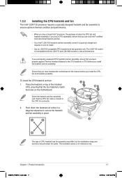
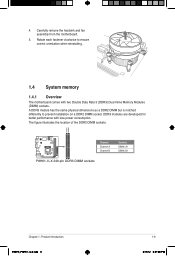
... should remain the same. The LGA1155 socket is for reference only. To install the CPU heatsink and fan: A 1. Place the heatsink on the motherboard. A B 1 1 B A The type of the installed CPU, ensuring that you use only Intel®‑certified multi‑directional heatsink and... fan. • Your Intel® LGA1155 heatsink and fan assembly comes in size and dimension. Chapter 1: Product introduction E6873_P8H61-I LX.indb 7 1-7 2/15/12 6:37:04 PM 1.3.2 Installing the CPU heatsink and fan The Intel® LGA1155 processor requires a specially designed...
... should remain the same. The LGA1155 socket is for reference only. To install the CPU heatsink and fan: A 1. Place the heatsink on the motherboard. A B 1 1 B A The type of the installed CPU, ensuring that you use only Intel®‑certified multi‑directional heatsink and... fan. • Your Intel® LGA1155 heatsink and fan assembly comes in size and dimension. Chapter 1: Product introduction E6873_P8H61-I LX.indb 7 1-7 2/15/12 6:37:04 PM 1.3.2 Installing the CPU heatsink and fan The Intel® LGA1155 processor requires a specially designed...

User Manual
Page 18
... can occur if you fail to the connector on the motherboard. 2. Rotate each fastener counterclockwise. 3. Disconnect the CPU fan cable from the motherboard. A B A B B A B A 1-8 E6873_P8H61-I LX.indb 8 ASUS P8H61-I LX CPU fan connector Do not forget to disengage the heatsink and fan assembly from the connector on the motherboard labeled CPU_FAN. Pull up two fasteners at a time in...
... can occur if you fail to the connector on the motherboard. 2. Rotate each fastener counterclockwise. 3. Disconnect the CPU fan cable from the motherboard. A B A B B A B A 1-8 E6873_P8H61-I LX.indb 8 ASUS P8H61-I LX CPU fan connector Do not forget to disengage the heatsink and fan assembly from the connector on the motherboard labeled CPU_FAN. Pull up two fasteners at a time in...
User Manual
Page 19
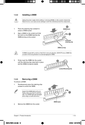
... dimensions as a DDR2 DIMM but is notched differently to ensure correct orientation when reinstalling. 1.4 System memory 1.4.1 Overview The motherboard comes with less power consumption. The figure illustrates the location of the DDR3 DIMM sockets: DIMMA1 DIMMB1 P8H61-I LX Channel Channel A Channel B P8H61-I LX 240-pin DDR3 DIMM sockets Sockets DIMM_A1 DIMM_B1 Chapter 1: Product introduction E6873_P8H61...
... dimensions as a DDR2 DIMM but is notched differently to ensure correct orientation when reinstalling. 1.4 System memory 1.4.1 Overview The motherboard comes with less power consumption. The figure illustrates the location of the DDR3 DIMM sockets: DIMMA1 DIMMB1 P8H61-I LX Channel Channel A Channel B P8H61-I LX 240-pin DDR3 DIMM sockets Sockets DIMM_A1 DIMM_B1 Chapter 1: Product introduction E6873_P8H61...

User Manual
Page 20
... H5TQ2G83AFR 7 1.5V • • Micron MT8JTF12864AZ-1G1F1 1GB SS Micron 9GF22D9KPT 7 - • • Micron MT16JTF25664AZ-1G1F1 2GB DS Micron 9HF22D9KPT 7 • • 1-10 E6873_P8H61-I LX.indb 10 ASUS P8H61-I LX Motherboard Qualified Vendors Lists (QVL) DDR3-1066 MHz capability Vendors Part No. 1.4.2 Memory configurations You may install 512MB, 1GB, 2GB, 4GB and 8GB unbuffered non...
... H5TQ2G83AFR 7 1.5V • • Micron MT8JTF12864AZ-1G1F1 1GB SS Micron 9GF22D9KPT 7 - • • Micron MT16JTF25664AZ-1G1F1 2GB DS Micron 9HF22D9KPT 7 • • 1-10 E6873_P8H61-I LX.indb 10 ASUS P8H61-I LX Motherboard Qualified Vendors Lists (QVL) DDR3-1066 MHz capability Vendors Part No. 1.4.2 Memory configurations You may install 512MB, 1GB, 2GB, 4GB and 8GB unbuffered non...
User Manual
Page 23
.... 2 Support the DIMM lightly with your fingers when pressing the retaining 1 clips. Simultaneously press the retaining clips outward to both the motherboard and the components. 1. DIMM notch Chapter 1: Product introduction E6873_P8H61-I LX.indb 13 1-13 2/15/12 6:37:16 PM 1.4.3 Installing a DIMM Unplug the power supply before adding or removing DIMMs or...
.... 2 Support the DIMM lightly with your fingers when pressing the retaining 1 clips. Simultaneously press the retaining clips outward to both the motherboard and the components. 1. DIMM notch Chapter 1: Product introduction E6873_P8H61-I LX.indb 13 1-13 2/15/12 6:37:16 PM 1.4.3 Installing a DIMM Unplug the power supply before adding or removing DIMMs or...

User Manual
Page 24
Align the card connector with the PCI Express specifications. 1-14 E6873_P8H61-I LX.indb 14 ASUS P8H61-I LX 2/15/12 6:37:16 PM Assign an IRQ to install expansion cards. When using PCI cards on BIOS setup. 2. Remove the bracket opposite ... card. Unplug the power cord before adding or removing expansion cards. Before installing the expansion card, read the documentation that you physical injury and damage motherboard components. 1.5.1 Installing an expansion card To install an expansion card: 1. Secure the card to use . 4. Keep the screw for the card. 2. 1.5 Expansion ...
Align the card connector with the PCI Express specifications. 1-14 E6873_P8H61-I LX.indb 14 ASUS P8H61-I LX 2/15/12 6:37:16 PM Assign an IRQ to install expansion cards. When using PCI cards on BIOS setup. 2. Remove the bracket opposite ... card. Unplug the power cord before adding or removing expansion cards. Before installing the expansion card, read the documentation that you physical injury and damage motherboard components. 1.5.1 Installing an expansion card To install an expansion card: 1. Secure the card to use . 4. Keep the screw for the card. 2. 1.5 Expansion ...

User Manual
Page 27
... audio module to this connector. 6. These two 4-pin Universal Serial Bus (USB) ports are for details. Connect one end of the motherboard's high-definition audio capability. • If you want to connect a high-definition front panel audio module to this connector, set to CRT...PORT1 L AGND Line out_L NC Line out_R MICPWR MIC2 PIN 1 PIN 1 HD-audio-compliant Legacy ACʼ97 pin definition compliant definition P8H61-I LX P8H61-I LX Front panel audio connector • We recommend that supports either HD Audio or legacy AC`97 audio standard. See section 2.5.6 Onboard Devices...
... audio module to this connector. 6. These two 4-pin Universal Serial Bus (USB) ports are for details. Connect one end of the motherboard's high-definition audio capability. • If you want to connect a high-definition front panel audio module to this connector, set to CRT...PORT1 L AGND Line out_L NC Line out_R MICPWR MIC2 PIN 1 PIN 1 HD-audio-compliant Legacy ACʼ97 pin definition compliant definition P8H61-I LX P8H61-I LX Front panel audio connector • We recommend that supports either HD Audio or legacy AC`97 audio standard. See section 2.5.6 Onboard Devices...

User Manual
Page 29
... connectors, then install the module to the USB connectors. P8H61-I LX.indb 19 1-19 2/15/12 6:37:27 PM Doing so will damage the motherboard! Insufficient air flow inside the system may damage the motherboard components. Connect the USB module cable to any of the connector. P8H61-I LX USB78 PIN 1 USB+5V USB_P7USB_P7+ GND USB+5V...
... connectors, then install the module to the USB connectors. P8H61-I LX.indb 19 1-19 2/15/12 6:37:27 PM Doing so will damage the motherboard! Insufficient air flow inside the system may damage the motherboard components. Connect the USB module cable to any of the connector. P8H61-I LX USB78 PIN 1 USB+5V USB_P7USB_P7+ GND USB+5V...

User Manual
Page 32
... DVD information The Support DVD that comes with the motherboard package contains the drivers, software applications, and utilities that you can install to change at any time without notice. To run the DVD. 1-22 ASUS P8H61-I LX E6873_P8H61-I LX.indb 22 2/15/12 6:37:31 PM 1.8 ...Software support 1.8.1 Installing an operating system This motherboard supports Windows® XP / Vista / 7 Operating Systems (OS). The contents of your...
... DVD information The Support DVD that comes with the motherboard package contains the drivers, software applications, and utilities that you can install to change at any time without notice. To run the DVD. 1-22 ASUS P8H61-I LX E6873_P8H61-I LX.indb 22 2/15/12 6:37:31 PM 1.8 ...Software support 1.8.1 Installing an operating system This motherboard supports Windows® XP / Vista / 7 Operating Systems (OS). The contents of your...

User Manual
Page 33
...screen appears. Updating the BIOS To update the BIOS: 1. The AI Suite II Quick Bar appears. 2. Installing ASUS Update To install ASUS Update: 1. Copy the original motherboard BIOS using this utility. The Drivers menu appears. 2. From the list, select either through a network or an..., and update the motherboard BIOS in Windows® environment. • ASUS Update requires an Internet connection either of the original motherboard BIOS file to a USB flash disk in case you need to download then click Next. Chapter 2: BIOS information 2-1 E6873_P8H61-I LX.indb 1 2/15/...
...screen appears. Updating the BIOS To update the BIOS: 1. The AI Suite II Quick Bar appears. 2. Installing ASUS Update To install ASUS Update: 1. Copy the original motherboard BIOS using this utility. The Drivers menu appears. 2. From the list, select either through a network or an..., and update the motherboard BIOS in Windows® environment. • ASUS Update requires an Internet connection either of the original motherboard BIOS file to a USB flash disk in case you need to download then click Next. Chapter 2: BIOS information 2-1 E6873_P8H61-I LX.indb 1 2/15/...

User Manual
Page 35
...press to copy the current BIOS file that contains the latest BIOS, and then press . 5. The succeeding utility screens are for reference only. Prepare the motherboard support DVD and a USB flash drive in DOS environment 1. Press the Up/Down arrow keys to the USB port. 2. NTFS is done. •... at http://support.asus.com and save the BIOS file and BIOS Updater to show the BIOS Boot Device Select Menu. Press to switch to boot using defaults Chapter 2: BIOS information E6873_P8H61-I LX.indb 3 2-3 2/15/12 6:37:35 PM Booting the system in FAT32/16 format and single partition. 2....
...press to copy the current BIOS file that contains the latest BIOS, and then press . 5. The succeeding utility screens are for reference only. Prepare the motherboard support DVD and a USB flash drive in DOS environment 1. Press the Up/Down arrow keys to the USB port. 2. NTFS is done. •... at http://support.asus.com and save the BIOS file and BIOS Updater to show the BIOS Boot Device Select Menu. Press to switch to boot using defaults Chapter 2: BIOS information E6873_P8H61-I LX.indb 3 2-3 2/15/12 6:37:35 PM Booting the system in FAT32/16 format and single partition. 2....
User Manual
Page 38
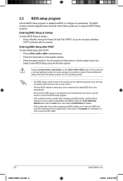
... to control the BIOS setup program. • If the system becomes unstable after changing any BIOS setting, try to clear the CMOS and reset the motherboard to the default value. See section 1.9 Jumpers for details. • If the system fails to boot after POST: • Press ++ simultaneously. •... system chassis. • Press the power button to turn the system off then back on how to erase the RTC RAM. 2-6 E6873_P8H61-I LX.indb 6 ASUS P8H61-I LX 2/15/12 6:37:37 PM Select the Load Optimized Defaults item under the Exit menu. Entering BIOS Setup at startup To enter BIOS Setup ...
... to control the BIOS setup program. • If the system becomes unstable after changing any BIOS setting, try to clear the CMOS and reset the motherboard to the default value. See section 1.9 Jumpers for details. • If the system fails to boot after POST: • Press ++ simultaneously. •... system chassis. • Press the power button to turn the system off then back on how to erase the RTC RAM. 2-6 E6873_P8H61-I LX.indb 6 ASUS P8H61-I LX 2/15/12 6:37:37 PM Select the Load Optimized Defaults item under the Exit menu. Entering BIOS Setup at startup To enter BIOS Setup ...

User Manual
Page 39
The default screen for details. EZ Mode Friday [10/08/2010] P8H61-I LX.indb 7 2/15/12 6:37:39 PM Selects the display language of the BIOS setup program Clicks to decide the boot priority. Chapter 2: BIOS information 2-7 E6873_P8H61-I LX BIOS Version : 0103 CPU Type : Intel(R) Core(TM) i5-2400 CPU @...Priority Energy Saving Normal Use the mouse to drag or keyboard to navigate to display all fan speeds if available Displays the CPU/motherboard temperature, CPU/5V/3.3V/12V voltage output, CPU/chassis fan speed Exits the BIOS setup program without saving the changes, saves ...
The default screen for details. EZ Mode Friday [10/08/2010] P8H61-I LX.indb 7 2/15/12 6:37:39 PM Selects the display language of the BIOS setup program Clicks to decide the boot priority. Chapter 2: BIOS information 2-7 E6873_P8H61-I LX BIOS Version : 0103 CPU Type : Intel(R) Core(TM) i5-2400 CPU @...Priority Energy Saving Normal Use the mouse to drag or keyboard to navigate to display all fan speeds if available Displays the CPU/motherboard temperature, CPU/5V/3.3V/12V voltage output, CPU/chassis fan speed Exits the BIOS setup program without saving the changes, saves ...


