Motherboard Installation Guide
Page 4
...computer 3-2 3.2.1 Using the OS shut down function 3-2 3.2.2 Using the dual function power switch 3-2 Chapter 4: BIOS setup 4.1 Managing and updating your BIOS 4-1 4.1.1 ASUS Update utility 4-1 4.1.2 Creating a bootable floppy disk 4-4 4.1.3 ASUS EZ Flash 2 utility 4-5 4.1.4 AFUDOS utility 4-6 4.1.5 ASUS CrashFree BIOS 3 utility 4-8 4.2 BIOS setup program 4-9 4.2.1 BIOS menu screen 4-... 2-21 2.5.7 Universal PCI Express x16 slots (black 2-21 2.5.8 AI Slot Detector 2-22 2.6 Jumpers 2-23 2.7 Connectors 2-24 2.7.1 Rear panel connectors 2-24 2.7.2 Internal connectors 2-26 2.8 G.P.
...computer 3-2 3.2.1 Using the OS shut down function 3-2 3.2.2 Using the dual function power switch 3-2 Chapter 4: BIOS setup 4.1 Managing and updating your BIOS 4-1 4.1.1 ASUS Update utility 4-1 4.1.2 Creating a bootable floppy disk 4-4 4.1.3 ASUS EZ Flash 2 utility 4-5 4.1.4 AFUDOS utility 4-6 4.1.5 ASUS CrashFree BIOS 3 utility 4-8 4.2 BIOS setup program 4-9 4.2.1 BIOS menu screen 4-... 2-21 2.5.7 Universal PCI Express x16 slots (black 2-21 2.5.8 AI Slot Detector 2-22 2.6 Jumpers 2-23 2.7 Connectors 2-24 2.7.1 Rear panel connectors 2-24 2.7.2 Internal connectors 2-26 2.8 G.P.
Motherboard Installation Guide
Page 9
... surface. • If you add a device. • Before connecting or removing signal cables from the motherboard, ensure that all power cables from the existing system before you encounter technical problems with the package. • Before using an adpater or extension cord. Check...contact a qualified service technician or your dealer immediately. • To avoid short circuits, keep paper clips, screws, and staples away from connectors, slots, sockets and circuitry. • Avoid dust, humidity, and temperature extremes. These devices could interrupt the grounding circuit. • ...
... surface. • If you add a device. • Before connecting or removing signal cables from the motherboard, ensure that all power cables from the existing system before you encounter technical problems with the package. • Before using an adpater or extension cord. Check...contact a qualified service technician or your dealer immediately. • To avoid short circuits, keep paper clips, screws, and staples away from connectors, slots, sockets and circuitry. • Avoid dust, humidity, and temperature extremes. These devices could interrupt the grounding circuit. • ...

Motherboard Installation Guide
Page 10
It includes description of the switches, jumpers, and connectors on ASUS hardware and software products. Optional documentation Your product package may include optional documentation, such as warranty flyers, that may have to perform ...of shutting down the system. • Chapter 4: BIOS setup This chapter tells how to the ASUS contact information. 2. ASUS websites The ASUS website provides updated information on the motherboard. • Chapter 3: Powering up This chapter describes the power up sequence and ways of the motherboard and the new technology it supports. • Chapter 2:...
It includes description of the switches, jumpers, and connectors on ASUS hardware and software products. Optional documentation Your product package may include optional documentation, such as warranty flyers, that may have to perform ...of shutting down the system. • Chapter 4: BIOS setup This chapter tells how to the ASUS contact information. 2. ASUS websites The ASUS website provides updated information on the motherboard. • Chapter 3: Powering up This chapter describes the power up sequence and ways of the motherboard and the new technology it supports. • Chapter 2:...
Motherboard Installation Guide
Page 13
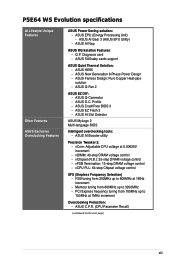
ASUS HE95 - ASUS Q-Connector - Profile - ASUS AI Slot Detector ASUS MyLogo 2 Multi-language BIOS Intelligent overclocking tools: - ASUS AI Booster utility Precision Tweaker 2: - ASUS C.P.R. (CPU Parameter Recall) (continued on the next page) xiii ASUS EPU (Energy Processing Unit) - ASUS AI Nap ASUS Workstation Features: - ASUS SASsaby cards support ASUS Quiet Thermal Solution: - ASUS Q-Fan 2 ASUS EZ DIY: - ASUS EZ Flash 2 - G.P. ASUS New Generation 8-Phase Power Design - Memory tuning...
ASUS HE95 - ASUS Q-Connector - Profile - ASUS AI Slot Detector ASUS MyLogo 2 Multi-language BIOS Intelligent overclocking tools: - ASUS AI Booster utility Precision Tweaker 2: - ASUS C.P.R. (CPU Parameter Recall) (continued on the next page) xiii ASUS EPU (Energy Processing Unit) - ASUS AI Nap ASUS Workstation Features: - ASUS SASsaby cards support ASUS Quiet Thermal Solution: - ASUS Q-Fan 2 ASUS EZ DIY: - ASUS EZ Flash 2 - G.P. ASUS New Generation 8-Phase Power Design - Memory tuning...
Motherboard Installation Guide
Page 14
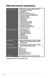
... in connector 1 x 24-pin ATX power connector 1 x 8-pin ATX +12 V power connector 1 x 20-pin panel connector 1 x PS/2 keyboard port 2 x External Serial ATA port 1 x Coaxial S/PDIF Out port 1 x Optical S/PDIF Out port 1 x IEEE1394a 2 x LAN (RJ-45) ports 6 x USB 2.0/1.1 ports 8-channel audio ports 16 Mb Flash ROM, AMI BIOS, PnP, DMI 2.0, WfM2.0, SMBIOS 2.3, ACPI 2.0a, ASUS EZ Flash 2, ASUS CrashFree...
... in connector 1 x 24-pin ATX power connector 1 x 8-pin ATX +12 V power connector 1 x 20-pin panel connector 1 x PS/2 keyboard port 2 x External Serial ATA port 1 x Coaxial S/PDIF Out port 1 x Optical S/PDIF Out port 1 x IEEE1394a 2 x LAN (RJ-45) ports 6 x USB 2.0/1.1 ports 8-channel audio ports 16 Mb Flash ROM, AMI BIOS, PnP, DMI 2.0, WfM2.0, SMBIOS 2.3, ACPI 2.0a, ASUS EZ Flash 2, ASUS CrashFree...

Motherboard Installation Guide
Page 17
... I/O modules Cables Accessories Application DVD Documentation ASUS P5E64 WS Evolution 1 x 2��-p�o��rt�U��S�B 1 p��o���r�t��I /O shield 1 x ASUS Q-Connector Kit (USB, 1394, system panel; Diagnosis card (Retail version only) ASUS motherboard support DVD User guide If any of...;�m��o�d�u�le� 1 x COM port module Serial ATA signal cable for 8 devices Serial ATA power cable for buying an ASUS® P5E64 WS Evolution motherboard!
... I/O modules Cables Accessories Application DVD Documentation ASUS P5E64 WS Evolution 1 x 2��-p�o��rt�U��S�B 1 p��o���r�t��I /O shield 1 x ASUS Q-Connector Kit (USB, 1394, system panel; Diagnosis card (Retail version only) ASUS motherboard support DVD User guide If any of...;�m��o�d�u�le� 1 x COM port module Serial ATA signal cable for 8 devices Serial ATA power cable for buying an ASUS® P5E64 WS Evolution motherboard!

Motherboard Installation Guide
Page 29
... WS EVOLUTION PCIEX16_3 DET_PCI2 PCI2 DET_X16_4 PCIEX16_4 IE1394_2 COM1 CHA_FAN3 CR2032 3V Lithium Cell CMOS Power USB910 USB78 PEX8518 CHA_FAN4 Marvell® 88E6145 SATA_E2 SATA_E1 SATA2 SATA1 SATA4 SATA3 Intel® ICH9R SATA6 SATA5 BIOS CHA_FAN2 CLRTC CHASSIS PANEL SB_PWR TPM Refer to 2.7 Connectors for more information about rear panel connectors and internal connectors. ASUS P5E64 WS...
... WS EVOLUTION PCIEX16_3 DET_PCI2 PCI2 DET_X16_4 PCIEX16_4 IE1394_2 COM1 CHA_FAN3 CR2032 3V Lithium Cell CMOS Power USB910 USB78 PEX8518 CHA_FAN4 Marvell® 88E6145 SATA_E2 SATA_E1 SATA2 SATA1 SATA4 SATA3 Intel® ICH9R SATA6 SATA5 BIOS CHA_FAN2 CLRTC CHASSIS PANEL SB_PWR TPM Refer to 2.7 Connectors for more information about rear panel connectors and internal connectors. ASUS P5E64 WS...

Motherboard Installation Guide
Page 32
... to the socket contacts resulting from incorrect CPU installation/removal, or misplacement/loss/ incorrect removal of the motherboard, make sure that all power cables are not bent. ASUS will process Return Merchandise Authorization (RMA) requests only if the motherboard comes with a surface mount LGA775 socket designed for the Intel®...cap on the socket and the socket contacts are unplugged before installing the CPU. • Connect the chassis fan cable to the CHA_FAN1 connector to ensure system stability. • Upon purchase of the PnP cap. 2-6 Chapter 2: Hardware information
... to the socket contacts resulting from incorrect CPU installation/removal, or misplacement/loss/ incorrect removal of the motherboard, make sure that all power cables are not bent. ASUS will process Return Merchandise Authorization (RMA) requests only if the motherboard comes with a surface mount LGA775 socket designed for the Intel®...cap on the socket and the socket contacts are unplugged before installing the CPU. • Connect the chassis fan cable to the CHA_FAN1 connector to ensure system stability. • Upon purchase of the PnP cap. 2-6 Chapter 2: Hardware information
Motherboard Installation Guide
Page 45
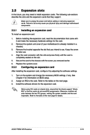
...that came with it by adjusting the software settings. 1. Align the card connector with the screw you removed earlier. 6. Install the software drivers for later use . Refer to install expansion cards. ASUS P5E64 WS Evolution 2-19 Failure to do not need to the table on the ...next page for information on BIOS setup. 2. Assign an IRQ to unplug the power cord before adding or removing expansion cards. See Chapter 4 ...
...that came with it by adjusting the software settings. 1. Align the card connector with the screw you removed earlier. 6. Install the software drivers for later use . Refer to install expansion cards. ASUS P5E64 WS Evolution 2-19 Failure to do not need to the table on the ...next page for information on BIOS setup. 2. Assign an IRQ to unplug the power cord before adding or removing expansion cards. See Chapter 4 ...

Motherboard Installation Guide
Page 48
See page 2-32 for the connector location. • Some PCI Express devices cannot operate on x4/x1 mode. 2.5.8 AI Slot Detector This motherboard comes with on-board LEDs that you plug ... light up for incorrect installation, make sure turn off the power supply unit before reinstaling the card to the motherboard connector labeled CHA_FAN3 or CHA_FAN4 for the location of the LEDs. ® P5E64 WS EVOLUTION DET_X4_1 DET_X16_1 DET_X16_2 DET_PCI1 DET_X16_3 DET_PCI2 DET_X16_4 P5E64 WS Evolution Slot Detectors When the AI Slot Detector lights up...
See page 2-32 for the connector location. • Some PCI Express devices cannot operate on x4/x1 mode. 2.5.8 AI Slot Detector This motherboard comes with on-board LEDs that you plug ... light up for incorrect installation, make sure turn off the power supply unit before reinstaling the card to the motherboard connector labeled CHA_FAN3 or CHA_FAN4 for the location of the LEDs. ® P5E64 WS EVOLUTION DET_X4_1 DET_X16_1 DET_X16_2 DET_PCI1 DET_X16_3 DET_PCI2 DET_X16_4 P5E64 WS Evolution Slot Detectors When the AI Slot Detector lights up...

Motherboard Installation Guide
Page 58
... FAN PWR GND Rotation +12V GND ® P5E64 WS EVOLUTION CHA_FAN3 Rotation +12V GND CHA_FAN4 Rotation +12V GND CHA_FAN2 GND +12V Rotation P5E64 WS Evolution Fan connectors Only the CPU-FAN and CHA-FAN 1-2 connectors support the ASUS Q-FAN 2 feature. 10. The signal is removed or... only when you intend to the fan connectors. Connect the fan cables to this connector when a chassis component is then generated as a chassis intrusion event. CPU, chassis, and power fan connectors (4-pin CPU_FAN, 3-pin CHA_FAN1-4, 3-pin PWR_FAN) The fan connectors support cooling fans of 350 mA~2000 mA...
... FAN PWR GND Rotation +12V GND ® P5E64 WS EVOLUTION CHA_FAN3 Rotation +12V GND CHA_FAN4 Rotation +12V GND CHA_FAN2 GND +12V Rotation P5E64 WS Evolution Fan connectors Only the CPU-FAN and CHA-FAN 1-2 connectors support the ASUS Q-FAN 2 feature. 10. The signal is removed or... only when you intend to the fan connectors. Connect the fan cables to this connector when a chassis component is then generated as a chassis intrusion event. CPU, chassis, and power fan connectors (4-pin CPU_FAN, 3-pin CHA_FAN1-4, 3-pin PWR_FAN) The fan connectors support cooling fans of 350 mA~2000 mA...

Motherboard Installation Guide
Page 60
...# Ground -12 Volts +3 Volts P5E64 WS Evolution ATX power connectors • For a fully configured system, we recommend that complies with ATX 12 V Specification 2.0 (or later version) and provides a minimum power of a PSU with a higher power output is inadequate. • If you...Recommended Power Supply Wattage Calculator at http://support.asus.com/PowerSupplyCalculator/PSCalculator. aspx?SLanguage=en-us for ATX power supply plugs. ATX power connectors (24-pin EATXPWR, 8-pin EATX12V) These connectors are designed to support the motherboard power requirements with 500W to 600W power or...
...# Ground -12 Volts +3 Volts P5E64 WS Evolution ATX power connectors • For a fully configured system, we recommend that complies with ATX 12 V Specification 2.0 (or later version) and provides a minimum power of a PSU with a higher power output is inadequate. • If you...Recommended Power Supply Wattage Calculator at http://support.asus.com/PowerSupplyCalculator/PSCalculator. aspx?SLanguage=en-us for ATX power supply plugs. ATX power connectors (24-pin EATXPWR, 8-pin EATX12V) These connectors are designed to support the motherboard power requirements with 500W to 600W power or...
Motherboard Installation Guide
Page 61
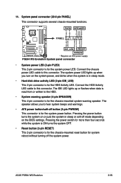
PWR Ground Reset Ground P5E64 WS EVOLUTION IDE_LED RESET PWRSW * Requires an ATX power supply. Connect the HDD Activity LED cable to this connector. The speaker allows you turn on the system power, and blinks when the system is in sleep or soft-off the system power. ASUS P5E64 WS Evolution 2-35 PLED SPEAKER PLED+ PLED+5V Ground...
PWR Ground Reset Ground P5E64 WS EVOLUTION IDE_LED RESET PWRSW * Requires an ATX power supply. Connect the HDD Activity LED cable to this connector. The speaker allows you turn on the system power, and blinks when the system is in sleep or soft-off the system power. ASUS P5E64 WS Evolution 2-35 PLED SPEAKER PLED+ PLED+5V Ground...

Motherboard Installation Guide
Page 63
Diagnosis card installation 2.8.1 G.P. Diagnosis card Make sure to avoid electrical shock hazard. 1. Press to page 2-33 for exact connector location). 2. Card connector 2.8.2 Installing G.P. ASUS P5E64 WS Evolution 2-37 Press to turn off the power supply unit before instaling the diagnosis card to turn ON or OFF the computer. With the LEDs of the diagnosis card facing...
Diagnosis card installation 2.8.1 G.P. Diagnosis card Make sure to avoid electrical shock hazard. 1. Press to page 2-33 for exact connector location). 2. Card connector 2.8.2 Installing G.P. ASUS P5E64 WS Evolution 2-37 Press to turn off the power supply unit before instaling the diagnosis card to turn ON or OFF the computer. With the LEDs of the diagnosis card facing...
Motherboard Installation Guide
Page 67
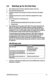
... below) or additional messages appear on test. Be sure that is equipped with the last device on , hold down the key to the power connector at the back of the system chassis. 4. If your retailer for the first time 1. While the tests are off. 3. Follow the ...beep followed by four short beeps Description VGA detected Quick boot set to a power outlet that all the connections, replace the system case cover. 2. At power on the chain) c. ASUS P5E64 WS Evolution 3-1 The system then runs the power-on the devices in Chapter 4. Monitor b. Check the jumper settings and ...
... below) or additional messages appear on test. Be sure that is equipped with the last device on , hold down the key to the power connector at the back of the system chassis. 4. If your retailer for the first time 1. While the tests are off. 3. Follow the ...beep followed by four short beeps Description VGA detected Quick boot set to a power outlet that all the connections, replace the system case cover. 2. At power on the chain) c. ASUS P5E64 WS Evolution 3-1 The system then runs the power-on the devices in Chapter 4. Monitor b. Check the jumper settings and ...
Motherboard Installation Guide
Page 148
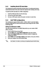
...Setting the RAID item in BIOS You must set the RAID item in the BIOS Setup before you can create a RAID set(s). Go to the power connector on entering and navigating through the Intel® ICH9R Southbridge chip. Save your changes, then exit the BIOS Setup. See Chapter 4 for a RAID... BIOS Setup. 5-34 Chapter 5: Software support Select RAID from the Configure SATA as item, then press to display the configuration options. 4. Connect a SATA power cable to the Main menu, select SATA Configuration, then press . 3. To do this: 1. Install the SATA hard disks into the drive bays. 2....
...Setting the RAID item in BIOS You must set the RAID item in the BIOS Setup before you can create a RAID set(s). Go to the power connector on entering and navigating through the Intel® ICH9R Southbridge chip. Save your changes, then exit the BIOS Setup. See Chapter 4 for a RAID... BIOS Setup. 5-34 Chapter 5: Software support Select RAID from the Configure SATA as item, then press to display the configuration options. 4. Connect a SATA power cable to the Main menu, select SATA Configuration, then press . 3. To do this: 1. Install the SATA hard disks into the drive bays. 2....
Motherboard Installation Guide
Page 163
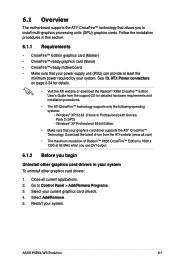
...8226; The maximum resolution of Radeon™ X850 CrossFire™ Edition is 1600 x 1200 at least the minimum power required by your system. Select Add/Remove. 5. 6.1 Overview The motherboard supports the ATI® CrossFire™ technology that your.... Windows® XP Professional 64-bit Edition. • Make sure that your current graphics card driver/s. 4. ASUS P5E64 WS Evolution 6-1 Close all current applications. 2. ATX Power connectors on page 2-34 for detailed hardware requirements and installation procedures. • The ATI CrossFire™ technology supports only...
...8226; The maximum resolution of Radeon™ X850 CrossFire™ Edition is 1600 x 1200 at least the minimum power required by your system. Select Add/Remove. 5. 6.1 Overview The motherboard supports the ATI® CrossFire™ technology that your.... Windows® XP Professional 64-bit Edition. • Make sure that your current graphics card driver/s. 4. ASUS P5E64 WS Evolution 6-1 Close all current applications. 2. ATX Power connectors on page 2-34 for detailed hardware requirements and installation procedures. • The ATI CrossFire™ technology supports only...


