
User Manual
Page 16
...1-23 1-27 1-28 1-27 1-25 1-26 1-4 1-6 Chapter 1: Product introduction CPU fan connector (4-pin CPU_FAN) 6. IDE connector (40-pin PRI_IDE) 8. ATX power connectors (24-pin EATXPWR, 4-pin ATX12V) 3. Speaker connector (4-pin SPEAKER) Page 1-21 9. 1-25 10. USB connectors (10-1 pin USB56 and ...USB78) 1-7 12. System panel connector (10-1 pin F_PANEL) 1-26 13. Connectors/Jumpers/Slots/LED Clear RTC RAM (3-pin CLRTC) Serial ATA connectors (7-pin SATA1-4) 1-21 11. DDR2 DIMM slots 7. 1.5.3 Motherboard layout 12 3 4 5 6 7 2 8 9 16 15 14 13 12 11 3 10 1.5.4 Layout contents...
...1-23 1-27 1-28 1-27 1-25 1-26 1-4 1-6 Chapter 1: Product introduction CPU fan connector (4-pin CPU_FAN) 6. IDE connector (40-pin PRI_IDE) 8. ATX power connectors (24-pin EATXPWR, 4-pin ATX12V) 3. Speaker connector (4-pin SPEAKER) Page 1-21 9. 1-25 10. USB connectors (10-1 pin USB56 and ...USB78) 1-7 12. System panel connector (10-1 pin F_PANEL) 1-26 13. Connectors/Jumpers/Slots/LED Clear RTC RAM (3-pin CLRTC) Serial ATA connectors (7-pin SATA1-4) 1-21 11. DDR2 DIMM slots 7. 1.5.3 Motherboard layout 12 3 4 5 6 7 2 8 9 16 15 14 13 12 11 3 10 1.5.4 Layout contents...

User Manual
Page 30
... limitation, AC power off and on the power supply or unplug and plug the power cord before you to clear the Real Time Clock (RTC) RAM in CMOS, which include system setup information such as system passwords. function. You can clear the CMOS memory of date, time, and system setup ...clear the RTC when the system hangs due to overclocking, use the C.P.R. You must turn ON the computer. 4. The onboard button cell battery powers the RAM data in CMOS. Plug the power cord and turn off is required before rebooting the system. 1-20 Chapter 1: Product introduction To erase the RTC...
... limitation, AC power off and on the power supply or unplug and plug the power cord before you to clear the Real Time Clock (RTC) RAM in CMOS, which include system setup information such as system passwords. function. You can clear the CMOS memory of date, time, and system setup ...clear the RTC when the system hangs due to overclocking, use the C.P.R. You must turn ON the computer. 4. The onboard button cell battery powers the RAM data in CMOS. Plug the power cord and turn off is required before rebooting the system. 1-20 Chapter 1: Product introduction To erase the RTC...

User Manual
Page 44
...recovered BIOS may not be smaller than 8GB. • DO NOT shut down the system properly from the ASUS website at www.asus.com. 2.2 BIOS setup program This motherboard supports a programmable Serial Peripheral Interface (SPI) chip that the computer can cause damage to enter the Setup... ++ simultaneously. • Press the reset button on the motherboard stores the Setup utility. The Setup program is designed to make your computer in the CMOS RAM of the following procedures: • Restart using this motherboard. Restart the system after POST, reboot the system by doing...
...recovered BIOS may not be smaller than 8GB. • DO NOT shut down the system properly from the ASUS website at www.asus.com. 2.2 BIOS setup program This motherboard supports a programmable Serial Peripheral Interface (SPI) chip that the computer can cause damage to enter the Setup... ++ simultaneously. • Press the reset button on the motherboard stores the Setup utility. The Setup program is designed to make your computer in the CMOS RAM of the following procedures: • Restart using this motherboard. Restart the system after POST, reboot the system by doing...
User Manual
Page 55
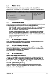
... to be used for Advanced Configuration and Power Interface (ACPI) 2.0 specifications. Configuration options: [Disabled] [Enabled] ASUS P5QPL-AM 2-15 Configuration options: [S1 (POS) Only] [S3 Only] [Auto] [S1(POS) Only] -... working state exactly where it was before the AC power loss. This feature requires an ATX power supply that provides at any time. [S3 Only] - In S1 sleep state,...disabe the PS/2 keyboard/mouse to generate a wake event. Select an item then press to RAM) sleep state (default). Configuration options: [Disabled] [Enabled] 2.5.4 APM Configuration Restore on state,...
... to be used for Advanced Configuration and Power Interface (ACPI) 2.0 specifications. Configuration options: [Disabled] [Enabled] ASUS P5QPL-AM 2-15 Configuration options: [S1 (POS) Only] [S3 Only] [Auto] [S1(POS) Only] -... working state exactly where it was before the AC power loss. This feature requires an ATX power supply that provides at any time. [S3 Only] - In S1 sleep state,...disabe the PS/2 keyboard/mouse to generate a wake event. Select an item then press to RAM) sleep state (default). Configuration options: [Disabled] [Enabled] 2.5.4 APM Configuration Restore on state,...

User Manual
Page 58
...The message Password uninstalled appears. User Access Level [Full Access] This item allows you to select the access restriction to erase the RTC RAM. allows viewing and changing all the fields in a password containing up to any field. [Limited] - To change to six letters or...1. The message Password Installed appears after you set your BIOS password, you can clear it by erasing the CMOS Real Time Clock (RTC) RAM. Change User Password Select this item shows Installed. To set a Supervisor Password: 1. Confirm the password when prompted. The User Password item on...
...The message Password uninstalled appears. User Access Level [Full Access] This item allows you to select the access restriction to erase the RTC RAM. allows viewing and changing all the fields in a password containing up to any field. [Limited] - To change to six letters or...1. The message Password Installed appears after you set your BIOS password, you can clear it by erasing the CMOS Real Time Clock (RTC) RAM. Change User Password Select this item shows Installed. To set a Supervisor Password: 1. Confirm the password when prompted. The User Password item on...

User Manual
Page 60
...appears. Select+FFEEFFEo-11Sn11Sn0Ct0CeeorSSCGSEf eeheaxtSSGGSEhllanvieeoeaxeeeneetllnviccgroeeteettteaapccorlntttaaioSIOdSlnnctpHSIudsreteEctbHemilxfre-eEreopioemslxnntmecpinrtteheisn Exit & Save Changes Once you are saved to the CMOS RAM. Discard Changes This option allows you to discard the selections you made to the Setup program....optimal or failsafe default values for a confirmation before saving the values to the non-volatile RAM. 2-20 Chapter 2: BIOS information F1F010kekyeycacnanbebeusuesded fofrorthtihsisopoepreartaitoino.n. Select OK to discard any changes and...
...appears. Select+FFEEFFEo-11Sn11Sn0Ct0CeeorSSCGSEf eeheaxtSSGGSEhllanvieeoeaxeeeneetllnviccgroeeteettteaapccorlntttaaioSIOdSlnnctpHSIudsreteEctbHemilxfre-eEreopioemslxnntmecpinrtteheisn Exit & Save Changes Once you are saved to the CMOS RAM. Discard Changes This option allows you to discard the selections you made to the Setup program....optimal or failsafe default values for a confirmation before saving the values to the non-volatile RAM. 2-20 Chapter 2: BIOS information F1F010kekyeycacnanbebeusuesded fofrorthtihsisopoepreartaitoino.n. Select OK to discard any changes and...


