
User Manual
Page 10
P5P41T LE specifications summary Rear panel ports Internal connectors BIOS features Manageability Accessories Support DVD Form... USB 2.0 ports 1 x CPU fan connector 1 x Chassis fan connector 1 x IDE connector 1 x 24-pin EATX Power connector 1 x 4-pin ATX 12V Power connector 4 x SATA connectors 8 Mb Flash ROM, AMI BIOS, PnP, DMI v2.0, WfM2.0, SMBIOS v2.5, ACPI v2 0a WOL, PXE,...UltraDMA 100/66/33 cable 2 x Serial ATA cables 1 x I/O shield User Manual Drivers ASUS Update ASUS PC Probe II Anti-virus software (OEM version) ATX form factor: 12 in x7.2 in (30.5 cm x 18.3cm) *Specifications are subject ...
P5P41T LE specifications summary Rear panel ports Internal connectors BIOS features Manageability Accessories Support DVD Form... USB 2.0 ports 1 x CPU fan connector 1 x Chassis fan connector 1 x IDE connector 1 x 24-pin EATX Power connector 1 x 4-pin ATX 12V Power connector 4 x SATA connectors 8 Mb Flash ROM, AMI BIOS, PnP, DMI v2.0, WfM2.0, SMBIOS v2.5, ACPI v2 0a WOL, PXE,...UltraDMA 100/66/33 cable 2 x Serial ATA cables 1 x I/O shield User Manual Drivers ASUS Update ASUS PC Probe II Anti-virus software (OEM version) ATX form factor: 12 in x7.2 in (30.5 cm x 18.3cm) *Specifications are subject ...
User Manual
Page 14
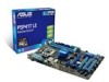
...the following precautions before you install motherboard components or change any motherboard settings. • Unplug the power cord from the power supply. P5P41T LE SB_PWR ON OFF Standby Power Powered Off P5P41T LE Onboard LED 1-4 Chapter 1: Product introduction This is a reminder that you must shut down the system and unplug the power cable ... any motherboard component. 1.4 Before you proceed Take note of the onboard LED. Failure to do so may cause severe damage to indicate that the ATX power supply is switched off or the power cord is ON, in sleep mode, or in soft-off mode.
...the following precautions before you install motherboard components or change any motherboard settings. • Unplug the power cord from the power supply. P5P41T LE SB_PWR ON OFF Standby Power Powered Off P5P41T LE Onboard LED 1-4 Chapter 1: Product introduction This is a reminder that you must shut down the system and unplug the power cable ... any motherboard component. 1.4 Before you proceed Take note of the onboard LED. Failure to do so may cause severe damage to indicate that the ATX power supply is switched off or the power cord is ON, in sleep mode, or in soft-off mode.
User Manual
Page 16
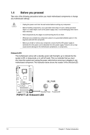
...USB34 LGA775 PRI_IDE 5 30.5cm(12.0in) LAN1_USB12 CHA_FAN Intel® G41 AUDIO ICS 9LRS954 1 EATXPWR ATHEROS AR8121 PCIEX1_1 P5P41T LE PCIEX16_1 Super I/O PCIEX1_2 Lithium Cell CMOS Power ALC 662 AAFP SPDIF_OUT 13 12 PCI1 PCI2 PCI3 Intel® ICH7 SATA1 SATA2...9 1.5.4 Layout contents Connectors/Jumpers/Slots Page Connectors/Jumpers/Slots Page 1. IDE connector (40-1 pin PRI_IDE) 1-23 12. pin SPEAKER) 1-22 4. ATX power connectors (24-pin EATXPWR, 4-pin 1-21 8. CPU and chassis fan connectors (4-pin CPU_FAN, 3-pin CHA_FAN) 1-20 9. Digital audio connector (4-1...
...USB34 LGA775 PRI_IDE 5 30.5cm(12.0in) LAN1_USB12 CHA_FAN Intel® G41 AUDIO ICS 9LRS954 1 EATXPWR ATHEROS AR8121 PCIEX1_1 P5P41T LE PCIEX16_1 Super I/O PCIEX1_2 Lithium Cell CMOS Power ALC 662 AAFP SPDIF_OUT 13 12 PCI1 PCI2 PCI3 Intel® ICH7 SATA1 SATA2...9 1.5.4 Layout contents Connectors/Jumpers/Slots Page Connectors/Jumpers/Slots Page 1. IDE connector (40-1 pin PRI_IDE) 1-23 12. pin SPEAKER) 1-22 4. ATX power connectors (24-pin EATXPWR, 4-pin 1-21 8. CPU and chassis fan connectors (4-pin CPU_FAN, 3-pin CHA_FAN) 1-20 9. Digital audio connector (4-1...

User Manual
Page 31
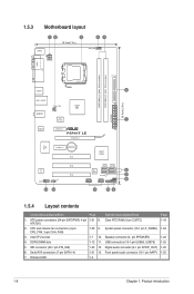
... GND +3 Volts +12 Volts +12 Volts +5V Standby Power OK PIN 1 GND +5 Volts GND +5 Volts GND +3 Volts +3 Volts PIN 1 P5P41T LE ATX power connectors GND +5 Volts +5 Volts +5 Volts -5 Volts GND GND GND PSON# GND -12 Volts +3 Volts • For a fully configured system, we...ATA connectors (7-pin SATA1-4) These connectors are for the Serial ATA signal cables for ATX power supply plugs. The system may become unstable or may not boot up if the power is inadequate. 4. ASUS P5P41T LE 1-21 Find the proper orientation and push down firmly until the connectors completely fit....
... GND +3 Volts +12 Volts +12 Volts +5V Standby Power OK PIN 1 GND +5 Volts GND +5 Volts GND +3 Volts +3 Volts PIN 1 P5P41T LE ATX power connectors GND +5 Volts +5 Volts +5 Volts -5 Volts GND GND GND PSON# GND -12 Volts +3 Volts • For a fully configured system, we...ATA connectors (7-pin SATA1-4) These connectors are for the Serial ATA signal cables for ATX power supply plugs. The system may become unstable or may not boot up if the power is inadequate. 4. ASUS P5P41T LE 1-21 Find the proper orientation and push down firmly until the connectors completely fit....


