
User Manual
Page 34
PMC Pm49FL004T LPC/FWH File Name to Program: M2A-VM HDMI.bin Flashing Complete Press to Program: M2A-VM HDMI.bin Programming Flash Memory - 7 BIOS N BIOS 8 BIOS BIOS AwardBIOS Flash Utility for ASUS V1.14 (C) Phoenix Technologies Ltd. All Rights Reserved For C51PV-MCP51-M2A-VM HDMI-00 DATE:04/13/2006 Flash Type - All Rights...
PMC Pm49FL004T LPC/FWH File Name to Program: M2A-VM HDMI.bin Flashing Complete Press to Program: M2A-VM HDMI.bin Programming Flash Memory - 7 BIOS N BIOS 8 BIOS BIOS AwardBIOS Flash Utility for ASUS V1.14 (C) Phoenix Technologies Ltd. All Rights Reserved For C51PV-MCP51-M2A-VM HDMI-00 DATE:04/13/2006 Flash Type - All Rights...
User Manual
Page 3
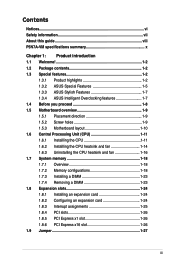
Contents Notices...vi Safety information vii About this guide viii P5N7A-VM specifications summary x Chapter 1: Product introduction 1.1 Welcome 1-2 1.2 Package contents 1-2 1.3 Special features 1-2 1.3.1 Product highlights 1-2 1.3.2 ASUS Special Features 1-5 1.3.3 ASUS Stylish Features 1-7 1.3.4 ASUS Intelligent Overclocking features 1-7 1.4 Before you proceed 1-8 1.5 Motherboard overview 1-9 1.5.1 Placement direction 1-9 1.5.2 Screw holes 1-9 1.5.3 Motherboard layout 1-10 1.6 Central Processing Unit (CPU 1-11 1.6.1 Installling the CPU 1-11 1.6.2 Installling the CPU...
Contents Notices...vi Safety information vii About this guide viii P5N7A-VM specifications summary x Chapter 1: Product introduction 1.1 Welcome 1-2 1.2 Package contents 1-2 1.3 Special features 1-2 1.3.1 Product highlights 1-2 1.3.2 ASUS Special Features 1-5 1.3.3 ASUS Stylish Features 1-7 1.3.4 ASUS Intelligent Overclocking features 1-7 1.4 Before you proceed 1-8 1.5 Motherboard overview 1-9 1.5.1 Placement direction 1-9 1.5.2 Screw holes 1-9 1.5.3 Motherboard layout 1-10 1.6 Central Processing Unit (CPU 1-11 1.6.1 Installling the CPU 1-11 1.6.2 Installling the CPU...
User Manual
Page 10
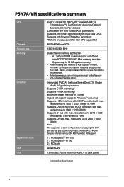
...Intel® Hyper-Threading Technology *Refer to 2048 x 1536 @horizontal 115KHz/vertical 75Hz Supports DP with max. P5N7A-VM specifications summary CPU Chipset System bus Memory Graphics Expansion slots LAN USB LGA775 socket for Intel® Core™2 Quad/Core™2 Extreme/Core™2 ...dual-core/Celeron® dual-core/Celeron® processors Compatible with max. resolution up to www.asus.com for the Memory QVL (Qualified Vendors Lists). Hence, a total installed memory of 512MB Hybrid SLI support (supports Windows® Vista only) Supports HDMI interface with HDCP compliant ...
...Intel® Hyper-Threading Technology *Refer to 2048 x 1536 @horizontal 115KHz/vertical 75Hz Supports DP with max. P5N7A-VM specifications summary CPU Chipset System bus Memory Graphics Expansion slots LAN USB LGA775 socket for Intel® Core™2 Quad/Core™2 Extreme/Core™2 ...dual-core/Celeron® dual-core/Celeron® processors Compatible with max. resolution up to www.asus.com for the Memory QVL (Qualified Vendors Lists). Hence, a total installed memory of 512MB Hybrid SLI support (supports Windows® Vista only) Supports HDMI interface with HDCP compliant ...

User Manual
Page 30
... Populated Populated DIMM_B2 - - - Populated 1-18 Chapter 1: Product Introduction 1.7 System memory 1.7.1 Overview The motherboard comes with four Double Data Rate 2 (DDR2) Dual Inline Memory Modules (DIMM) sockets. The figure illustrates the location of the DDR2 DIMM sockets: DIMM_B1 DIMM_B2 DIMM_A1 DIMM_A2 128 Pins 112 Pins P5N7A-VM P5N7A-VM 240-pin DDR2 DIMM Sockets Channel Channel A Channel B Sockets...
... Populated Populated DIMM_B2 - - - Populated 1-18 Chapter 1: Product Introduction 1.7 System memory 1.7.1 Overview The motherboard comes with four Double Data Rate 2 (DDR2) Dual Inline Memory Modules (DIMM) sockets. The figure illustrates the location of the DDR2 DIMM sockets: DIMM_B1 DIMM_B2 DIMM_A1 DIMM_A2 128 Pins 112 Pins P5N7A-VM P5N7A-VM 240-pin DDR2 DIMM Sockets Channel Channel A Channel B Sockets...
User Manual
Page 31
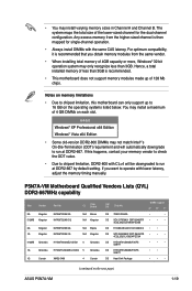
... the same vendor. • When installing total memory of 4 GB DIMMs on the next page) ASUS P5N7A-VM 1-19 If you obtain memory modules from the higher-sized channel is then mapped for the dual-channel configuration. P5N7A-VM Motherboard Qualified Vendors Lists (QVL) DDR2-667MHz capability Size Vendor ... downgrade to 16 GB on the operating systems listed below. Hence, a total installed memory of less than 3GB. For optimum compatibility, it is recommended. • This motherboard does not support memory modules made up to run at DDR2-667. You may install a maximum of 4GB...
... the same vendor. • When installing total memory of 4 GB DIMMs on the next page) ASUS P5N7A-VM 1-19 If you obtain memory modules from the higher-sized channel is then mapped for the dual-channel configuration. P5N7A-VM Motherboard Qualified Vendors Lists (QVL) DDR2-667MHz capability Size Vendor ... downgrade to 16 GB on the operating systems listed below. Hence, a total installed memory of less than 3GB. For optimum compatibility, it is recommended. • This motherboard does not support memory modules made up to run at DDR2-667. You may install a maximum of 4GB...

User Manual
Page 34
... 1G Super Talent 1G G.SKILL 1G G.SKILL 1G G.SKILL 2G G.SKILL 2G G.SKILL 4G G.SKILL 512MB(Kit of Dual-channel memory configuration. GX22GB6400DC GE22GB800C4DC GX22GB6400UDC GE22GB800C5DC GE24GB800C5QC GB24GB6400C5DC GX22GB6400LX GX24GB6400DC GE28GB800C4QC GX22GB6400CUSC GE24GB800C4DC T800UB1GC4 5 GEIL DS Heat-Sink Package 4 GEIL DS Heat...and black slots as two pairs of 2) G.SKILL 1G OCZ 2G OCZ 1G Elixir Part No. Visit the ASUS website for the latest DDR2-667/800 MHz QVL. 1-22 Chapter 1: Product Introduction CL Chip Brand SS/ DS Chip No. Single-...
... 1G Super Talent 1G G.SKILL 1G G.SKILL 1G G.SKILL 2G G.SKILL 2G G.SKILL 4G G.SKILL 512MB(Kit of Dual-channel memory configuration. GX22GB6400DC GE22GB800C4DC GX22GB6400UDC GE22GB800C5DC GE24GB800C5QC GB24GB6400C5DC GX22GB6400LX GX24GB6400DC GE28GB800C4QC GX22GB6400CUSC GE24GB800C4DC T800UB1GC4 5 GEIL DS Heat-Sink Package 4 GEIL DS Heat...and black slots as two pairs of 2) G.SKILL 1G OCZ 2G OCZ 1G Elixir Part No. Visit the ASUS website for the latest DDR2-667/800 MHz QVL. 1-22 Chapter 1: Product Introduction CL Chip Brand SS/ DS Chip No. Single-...
User Manual
Page 39
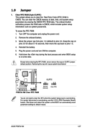
...cell battery powers the RAM data in CMOS. Plug the power cord and turn ON the computer. 6. P5N7A-VM P5N7A-VM Clear RTC RAM CLRTC 12 23 Normal (Default) Clear RTC You do not need to clear the RTC ...for about 5~10 seconds, then move the cap back to re-enter data. For system failure due to default values. ASUS P5N7A-VM 1-27 Shut down the key during the boot process and enter BIOS setup to pins 1-2. 4. Keep the cap on...Hold down and reboot the system so the BIOS can clear the CMOS memory of date, time, and system setup parameters by erasing the CMOS RTC RAM data.
...cell battery powers the RAM data in CMOS. Plug the power cord and turn ON the computer. 6. P5N7A-VM P5N7A-VM Clear RTC RAM CLRTC 12 23 Normal (Default) Clear RTC You do not need to clear the RTC ...for about 5~10 seconds, then move the cap back to re-enter data. For system failure due to default values. ASUS P5N7A-VM 1-27 Shut down the key during the boot process and enter BIOS setup to pins 1-2. 4. Keep the cap on...Hold down and reboot the system so the BIOS can clear the CMOS memory of date, time, and system setup parameters by erasing the CMOS RTC RAM data.
User Manual
Page 42
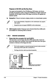
...motherboard. 17. Using the CPU/Memory of higher speed and bandwidth with a covered Pin 5. • The floppy disk drive cable is for connecting USB 2.0 devices. 1.10.2 Internal connectors 1. These two 4-pin Universal Serial Bus (USB) ports are available for the floppy disk drive (FDD) signal cable. FLOPPY PIN1 P5N7A-VM P5N7A-VM... Floppy Disk Drive Connector 1-30 Chapter 1: Product Introduction Playback of HD DVD and Blu-Ray Discs The speed and bandwidth of the CPU/Memory, DVD player, and drivers will upgrade the playback...
...motherboard. 17. Using the CPU/Memory of higher speed and bandwidth with a covered Pin 5. • The floppy disk drive cable is for connecting USB 2.0 devices. 1.10.2 Internal connectors 1. These two 4-pin Universal Serial Bus (USB) ports are available for the floppy disk drive (FDD) signal cable. FLOPPY PIN1 P5N7A-VM P5N7A-VM... Floppy Disk Drive Connector 1-30 Chapter 1: Product Introduction Playback of HD DVD and Blu-Ray Discs The speed and bandwidth of the CPU/Memory, DVD player, and drivers will upgrade the playback...
User Manual
Page 49
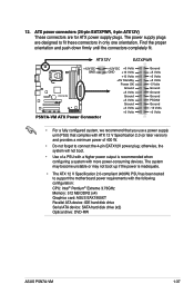
...; Pentium® Extreme 3.73GHz Memory: 512 MB DDR2 (x4) Graphics card: ASUS EAX1900XT Parallel ATA device: IDE hard disk drive Serial ATA device: SATA hard disk drive (x2) Optical drive: DVD-RW ASUS P5N7A-VM 1-37 ATX12V EATXPWR +12V DC GND P5N7A-VM P5N7A-VM ATX Power Connector +12V DC +3 ... provides a minimum power of a PSU with a higher power output is inadequate. • The ATX 12 V Specification 2.0-compliant (400W) PSU has been tested to support the motherboard power requirements with more power-consuming devices. Find the proper orientation and push down firmly until the ...
...; Pentium® Extreme 3.73GHz Memory: 512 MB DDR2 (x4) Graphics card: ASUS EAX1900XT Parallel ATA device: IDE hard disk drive Serial ATA device: SATA hard disk drive (x2) Optical drive: DVD-RW ASUS P5N7A-VM 1-37 ATX12V EATXPWR +12V DC GND P5N7A-VM P5N7A-VM ATX Power Connector +12V DC +3 ... provides a minimum power of a PSU with a higher power output is inadequate. • The ATX 12 V Specification 2.0-compliant (400W) PSU has been tested to support the motherboard power requirements with more power-consuming devices. Find the proper orientation and push down firmly until the ...

User Manual
Page 69
.... The BIOS automatically detects the items in this menu. System Memory Displays the auto-detected system memory. ASUS P5N7A-VM 2-17 Main BIOS SETUP UTILITY AMIBIOS Version : 0210 Build Date : 07/18/08 Processor Type Speed Count : Inter (R) Core(TM)2 CPU 6300 @ 1.86GHz : 1866 MHz : 2 System Memory Installed Size: 512MB Usable Size : 256MB Select Screen Select...
.... The BIOS automatically detects the items in this menu. System Memory Displays the auto-detected system memory. ASUS P5N7A-VM 2-17 Main BIOS SETUP UTILITY AMIBIOS Version : 0210 Build Date : 07/18/08 Processor Type Speed Count : Inter (R) Core(TM)2 CPU 6300 @ 1.86GHz : 1866 MHz : 2 System Memory Installed Size: 512MB Usable Size : 256MB Select Screen Select...
User Manual
Page 72
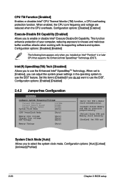
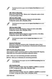
... enabled, the CPU core frequency and voltage are reduced when the CPU overheats. When set to [Enabled], you to overclock proportionally. [Unlink] Enter FSB and Memory clock manually. [Profiled] Set FSB and System Clock Mode [Auto] Allows you installed an Intel® Pentium® 4 or later CPU that supports the Enhanced...
... enabled, the CPU core frequency and voltage are reduced when the CPU overheats. When set to [Enabled], you to overclock proportionally. [Unlink] Enter FSB and Memory clock manually. [Profiled] Set FSB and System Clock Mode [Auto] Allows you installed an Intel® Pentium® 4 or later CPU that supports the Enhanced...
User Manual
Page 73
...1066] Allows you to set overclocking parameters. Configuration options: [Min.=400] [Max.=2500] Memory Clock (MHz) [666] Allows you to set overclocking parameters automatically. [Manual] - allows you to select the overclock profile. Memory Ratio [Auto] Allows you to enter an integer value from 400-2500 (MHz). iGPU OverClock... to enter an integer value from 400 to overclock for GPU. Overclock Profile [Auto] Allows you to individually set the memory frequency ranging from 1200MHz to 2000MHz to 1400 (MHz). Configuration options: [Min.=1200] [Max.=2000] ASUS P5N7A-VM 2-21
...1066] Allows you to set overclocking parameters. Configuration options: [Min.=400] [Max.=2500] Memory Clock (MHz) [666] Allows you to set overclocking parameters automatically. [Manual] - allows you to select the overclock profile. Memory Ratio [Auto] Allows you to enter an integer value from 400-2500 (MHz). iGPU OverClock... to enter an integer value from 400 to overclock for GPU. Overclock Profile [Auto] Allows you to individually set the memory frequency ranging from 1200MHz to 2000MHz to 1400 (MHz). Configuration options: [Min.=1200] [Max.=2000] ASUS P5N7A-VM 2-21

User Manual
Page 74
...1.85000V. Configuration options: [Auto] [1T] [2T] tRRD [Auto] Allows you to set the Memory Over Voltage. Configuration options:[Auto] [2] [3] [4] [5] [6] 2-22 Chapter 2: BIOS setup Memory Over Voltage [Auto] Allows you to set tRRD. The increment is set to set the Chipset Over...[Auto] Allows you to [Manual]. Use +/- to set tRP. Configuration options: [Auto] [Manual] The following items appear only when the Memory Timings item is 0.00625V. Configuration options:[Auto] [1] [2] [3] [4] [5] [6] [7] [8] tRC [Auto] Allows you to adjust the voltage. Configuration options: [Auto] [Min...
...1.85000V. Configuration options: [Auto] [1T] [2T] tRRD [Auto] Allows you to set the Memory Over Voltage. Configuration options:[Auto] [2] [3] [4] [5] [6] 2-22 Chapter 2: BIOS setup Memory Over Voltage [Auto] Allows you to set tRRD. The increment is set to set the Chipset Over...[Auto] Allows you to [Manual]. Use +/- to set tRP. Configuration options: [Auto] [Manual] The following items appear only when the Memory Timings item is 0.00625V. Configuration options:[Auto] [1] [2] [3] [4] [5] [6] [7] [8] tRC [Auto] Allows you to adjust the voltage. Configuration options: [Auto] [Min...


