

User Manual
Page 11
Doing so can damage the motherboard. 1.2.2 Layout contents Connectors/Jumpers/Slots Page Connectors/Jumpers/Slots 1. CPU fan connector (4-pin CPU_FAN) 1-12 9. Clear RTC RAM (3-pin CLRTC) 1-8 14. DO NOT overtighten the screws! Serial ATA connectors (7-pin SATA1-2) 1-10 13. Front panel audio connector (10-1 pin AAFP) Page 1-14 1-11 1-...
Doing so can damage the motherboard. 1.2.2 Layout contents Connectors/Jumpers/Slots Page Connectors/Jumpers/Slots 1. CPU fan connector (4-pin CPU_FAN) 1-12 9. Clear RTC RAM (3-pin CLRTC) 1-8 14. DO NOT overtighten the screws! Serial ATA connectors (7-pin SATA1-2) 1-10 13. Front panel audio connector (10-1 pin AAFP) Page 1-14 1-11 1-...

User Manual
Page 17
... BIOS setup to pins 1-2. 3. You can automatically reset parameter settings to clear the Real Time Clock (RTC) RAM in CMOS, which include system setup information such as system passwords. Clear RTC RAM (CLRTC) This jumper allows you to default values. Hold down and reboot the system so the BIOS can clear...system boot failure! • If the steps above do not need to clear the RTC when the system hangs due to clear the CMOS RTC RAM data. Turn OFF the computer and unplug the power cord. 2. 2. Keep the cap on CLRTC jumper default position. Except when clearing the RTC...
... BIOS setup to pins 1-2. 3. You can automatically reset parameter settings to clear the Real Time Clock (RTC) RAM in CMOS, which include system setup information such as system passwords. Clear RTC RAM (CLRTC) This jumper allows you to default values. Hold down and reboot the system so the BIOS can clear...system boot failure! • If the steps above do not need to clear the RTC when the system hangs due to clear the CMOS RTC RAM data. Turn OFF the computer and unplug the power cord. 2. 2. Keep the cap on CLRTC jumper default position. Except when clearing the RTC...
User Manual
Page 35
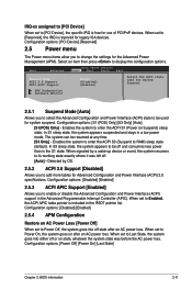
... system goes into either off state after an AC power loss. Configuration options: [PCI Device] [Reserved] 2.5 Power menu The Power menu items allow you to RAM) sleep state (default). Configuration options: [Power Off] [Power On] [Last State] Chapter 2: BIOS information 2-11
... system goes into either off state after an AC power loss. Configuration options: [PCI Device] [Reserved] 2.5 Power menu The Power menu items allow you to RAM) sleep state (default). Configuration options: [Power Off] [Power On] [Last State] Chapter 2: BIOS information 2-11
User Manual
Page 38
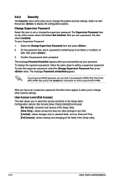
...other security settings. User Access Level [Full Access] This item allows you can clear it by erasing the CMOS Real Time Clock (RTC) RAM. allows changes only to display the configuration options. Change Supervisor Password Select this item shows Installed. To set a Supervisor Password: 1. On... user access to erase the RTC RAM. 2.6.3 Security The Security menu items allow you to change other items appear to allow change to any field. [Limited] - allows viewing and changing all the fields in the Setup utility. 2-14 ASUS P5KPL-AM IN/ROEM/SI The Supervisor Password item on how...
...other security settings. User Access Level [Full Access] This item allows you can clear it by erasing the CMOS Real Time Clock (RTC) RAM. allows changes only to display the configuration options. Change Supervisor Password Select this item shows Installed. To set a Supervisor Password: 1. On... user access to erase the RTC RAM. 2.6.3 Security The Security menu items allow you to change other items appear to allow change to any field. [Limited] - allows viewing and changing all the fields in the Setup utility. 2-14 ASUS P5KPL-AM IN/ROEM/SI The Supervisor Password item on how...

User Manual
Page 40
... to Sub-screen F1 General Help F10 Save and Exit Exit & Save Changes ESC Exit Once you are saved to the CMOS RAM. An onboard backup battery sustains the CMOS RAM so it stays on the Setup menus. After selecting this operation. Select OK to load default values. 2.8 Exit menu The Exit... & Save Changes or make other than System Date, System Time, and Password, the BIOS asks for a confirmation before saving the values to the non-volatile RAM. 2-16 ASUS P5KPL-AM IN/ROEM/SI
... to Sub-screen F1 General Help F10 Save and Exit Exit & Save Changes ESC Exit Once you are saved to the CMOS RAM. An onboard backup battery sustains the CMOS RAM so it stays on the Setup menus. After selecting this operation. Select OK to load default values. 2.8 Exit menu The Exit... & Save Changes or make other than System Date, System Time, and Password, the BIOS asks for a confirmation before saving the values to the non-volatile RAM. 2-16 ASUS P5KPL-AM IN/ROEM/SI


