
P5GD2 user's manual
Page 2
... the product is defaced or missing. or (2) the serial number of ASUSTeK COMPUTER INC. ("ASUS"). ASUS ASSUMES NO RESPONSIBILITY OR LIABILITY FOR ANY ERRORS OR INACCURACIES THAT MAY APPEAR IN THIS MANUAL, INCLUDING THE PRODUCTS AND SOFTWARE DESCRIBED IN IT. Product warranty or service will not be reproduced... THE POSSIBILITY OF SUCH DAMAGES ARISING FROM ANY DEFECT OR ERROR IN THIS MANUAL OR PRODUCT. E1738 First Edition August 2004 Copyright © 2004 ASUSTeK COMPUTER INC. All Rights Reserved. ASUS PROVIDES THIS MANUAL "AS IS" WITHOUT WARRANTY OF ANY KIND, EITHER EXPRESS OR IMPLIED, ...
... the product is defaced or missing. or (2) the serial number of ASUSTeK COMPUTER INC. ("ASUS"). ASUS ASSUMES NO RESPONSIBILITY OR LIABILITY FOR ANY ERRORS OR INACCURACIES THAT MAY APPEAR IN THIS MANUAL, INCLUDING THE PRODUCTS AND SOFTWARE DESCRIBED IN IT. Product warranty or service will not be reproduced... THE POSSIBILITY OF SUCH DAMAGES ARISING FROM ANY DEFECT OR ERROR IN THIS MANUAL OR PRODUCT. E1738 First Edition August 2004 Copyright © 2004 ASUSTeK COMPUTER INC. All Rights Reserved. ASUS PROVIDES THIS MANUAL "AS IS" WITHOUT WARRANTY OF ANY KIND, EITHER EXPRESS OR IMPLIED, ...

P5GD2 user's manual
Page 5
... Configuration 4-37 4.6.3 Security 4-38 4.7 Exit menu 4-41 Chapter 5: Software support 5.1 Installing an operating system 5-1 5.2 Support CD information 5-1 5.2.1 Running the support CD 5-1 5.2.2 Drivers menu 5-2 5.2.3 Utilities menu 5-3 5.2.4 Manuals menu 5-5 5.2.5 ASUS Contact information 5-6 5.2.6 Other information 5-6 v
... Configuration 4-37 4.6.3 Security 4-38 4.7 Exit menu 4-41 Chapter 5: Software support 5.1 Installing an operating system 5-1 5.2 Support CD information 5-1 5.2.1 Running the support CD 5-1 5.2.2 Drivers menu 5-2 5.2.3 Utilities menu 5-3 5.2.4 Manuals menu 5-5 5.2.5 ASUS Contact information 5-6 5.2.6 Other information 5-6 v
P5GD2 user's manual
Page 8
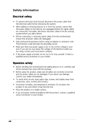
... all power cables from the system, ensure that came with the product, contact a qualified service technician or your retailer. viii If possible, disconnect all the manuals that the power cables for the devices are unplugged before the signal cables are not damaged.
... all power cables from the system, ensure that came with the product, contact a qualified service technician or your retailer. viii If possible, disconnect all the manuals that the power cables for the devices are unplugged before the signal cables are not damaged.

P5GD2 user's manual
Page 9
...provided. • Chapter 5: Software support This chapter describes the contents of the standard package. About this guide is organized This manual contains the following sources for additional information and for product and software updates. 1. How this guide This user guide contains the information... dealer. Detailed descriptions of the BIOS parameters are not part of the support CD that comes with the motherboard package. ASUS websites The ASUS website provides updated information on the motherboard. • Chapter 3: Powering up This chapter describes the power up sequence, the...
...provided. • Chapter 5: Software support This chapter describes the contents of the standard package. About this guide is organized This manual contains the following sources for additional information and for product and software updates. 1. How this guide This user guide contains the information... dealer. Detailed descriptions of the BIOS parameters are not part of the support CD that comes with the motherboard package. ASUS websites The ASUS website provides updated information on the motherboard. • Chapter 3: Powering up This chapter describes the power up sequence, the...

P5GD2 user's manual
Page 10
C A U T I M P O R T A N T : Instructions that you perform certain tasks properly, take note of the following symbols used throughout this manual. Typography Bold text Italics Command Indicates a menu or an item to select Used to emphasize a word or a phrase Keys enclosed in the less-than and ...
C A U T I M P O R T A N T : Instructions that you perform certain tasks properly, take note of the following symbols used throughout this manual. Typography Bold text Italics Command Indicates a menu or an item to select Used to emphasize a word or a phrase Keys enclosed in the less-than and ...

P5GD2 user's manual
Page 81
... system. Chipset Core Voltage [Auto] Allows selection of the CPU VCore voltage. Setting to Auto allows the BIOS to [AI N.O.S.] or [Manual]. Set to [Standard], [Sensitive], or [Heavy]. A very high Vcore voltage can severely damage the CPU! The following item appears only ... DDR SDRAM operating voltage. Refer to the DDR2 documentation before setting the CPU VCore voltage. Configuration options: [1.20V] [1.40V] [Auto] ASUS P5GD2 4-21 Memory Voltage [Auto] Allows selection of the CPU installed. Turbo NOS [Disabled] Disables or sets the overclocking threshold for the turbo...
... system. Chipset Core Voltage [Auto] Allows selection of the CPU VCore voltage. Setting to Auto allows the BIOS to [AI N.O.S.] or [Manual]. Set to [Standard], [Sensitive], or [Heavy]. A very high Vcore voltage can severely damage the CPU! The following item appears only ... DDR SDRAM operating voltage. Refer to the DDR2 documentation before setting the CPU VCore voltage. Configuration options: [1.20V] [1.40V] [Auto] ASUS P5GD2 4-21 Memory Voltage [Auto] Allows selection of the CPU installed. Turbo NOS [Disabled] Disables or sets the overclocking threshold for the turbo...

P5GD2 user's manual
Page 85
...[Disabled] [Enabled] 4.4.5 Chipset The Chipset menu allows you to the DRAM SPD (Serial Presence Detect). When disabled, you can manually set the DRAM timing parameters through the DRAM sub-items. The following sub-items appear when this item is Disabled. Advanced Chipset Settings... are set according to enable or disable the processor Hyper-Threading Technology. Configuration options: [2 Clocks] [3 Clocks] [4 Clocks] [5 Clocks] ASUS P5GD2 4-25 CPU Internal Thermal Control [Auto] Disables or sets the CPU internal thermal control. Select an item then press to the DDR SDRAM....
...[Disabled] [Enabled] 4.4.5 Chipset The Chipset menu allows you to the DRAM SPD (Serial Presence Detect). When disabled, you can manually set the DRAM timing parameters through the DRAM sub-items. The following sub-items appear when this item is Disabled. Advanced Chipset Settings... are set according to enable or disable the processor Hyper-Threading Technology. Configuration options: [2 Clocks] [3 Clocks] [4 Clocks] [5 Clocks] ASUS P5GD2 4-25 CPU Internal Thermal Control [Auto] Disables or sets the CPU internal thermal control. Select an item then press to the DDR SDRAM....

P5GD2 user's manual
Page 109
5.2.4 Manuals menu The Manuals menu contains a list of the user manual. • Most user manual files are in this menu may not be applicable for this motherboard model. ASUS P5GD2 5-5 Click an item to open the folder of supplementary user manuals. Install the Adobe® Acrobat® Reader from the U t i l i t i e s m e n u before opening a user manual file. • Some user manuals listed in Portable Document Format (PDF).
5.2.4 Manuals menu The Manuals menu contains a list of the user manual. • Most user manual files are in this menu may not be applicable for this motherboard model. ASUS P5GD2 5-5 Click an item to open the folder of supplementary user manuals. Install the Adobe® Acrobat® Reader from the U t i l i t i e s m e n u before opening a user manual file. • Some user manuals listed in Portable Document Format (PDF).

P5GD2 user's manual
Page 122
... SATA hard disks into the drive bays. 3. Connect a SATA power cable to the power connector on each drive. Connect the SATA signal cables. 3. See section "5.2.4 Manuals menu". 5-18 Chapter 5: Software support Set the jumpers of the same model and capacity when creating a disk array. Install the hard disks into the drive.../66 and Serial ATA hard disk drives. For optimal performance, install identical drives of each drive. Connect a 4-pin power cable to the RAID controllers user manual in the motherboard support CD for a RAID configuration: 1.
... SATA hard disks into the drive bays. 3. Connect a SATA power cable to the power connector on each drive. Connect the SATA signal cables. 3. See section "5.2.4 Manuals menu". 5-18 Chapter 5: Software support Set the jumpers of the same model and capacity when creating a disk array. Install the hard disks into the drive.../66 and Serial ATA hard disk drives. For optimal performance, install identical drives of each drive. Connect a 4-pin power cable to the RAID controllers user manual in the motherboard support CD for a RAID configuration: 1.


