User Manual
Page 16
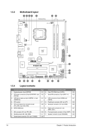
ATX power connectors (24-pin EATXPWR, 4-pin ATX12V) 3. Connectors/Jumpers/Slots/LED Clear RTC RAM (3-pin CLTRC) Serial ATA connectors (7-pin SATA 1-4) 1-21 ...DIMM slots 7. System panel connector (10-1 pin F_PANEL) Page 1-21 10. 1-25 11. CPU socket 5. 1.5.3 Motherboard layout 1 253 4 19.8cm(7.8in) 56 KBMS KBPWR CPU_FAN HDMI ATX12V DDR2 DIMM_A1 (64bit, 240-pin module) ...® G41 SPDIF_O ICS 9LRS954 AUDIO 2 PCIEX1_1 Lithium Cell CMOS Power EATXPWR Super I/O PCIEX16 P5G41-M PCI1 RTL Audio codec SPEAKER SPDIF_OUT COM1 AAFP PCI2 LPT USB56 Intel® ICH7 8Mb BIOS...
ATX power connectors (24-pin EATXPWR, 4-pin ATX12V) 3. Connectors/Jumpers/Slots/LED Clear RTC RAM (3-pin CLTRC) Serial ATA connectors (7-pin SATA 1-4) 1-21 ...DIMM slots 7. System panel connector (10-1 pin F_PANEL) Page 1-21 10. 1-25 11. CPU socket 5. 1.5.3 Motherboard layout 1 253 4 19.8cm(7.8in) 56 KBMS KBPWR CPU_FAN HDMI ATX12V DDR2 DIMM_A1 (64bit, 240-pin module) ...® G41 SPDIF_O ICS 9LRS954 AUDIO 2 PCIEX1_1 Lithium Cell CMOS Power EATXPWR Super I/O PCIEX16 P5G41-M PCI1 RTL Audio codec SPEAKER SPDIF_OUT COM1 AAFP PCI2 LPT USB56 Intel® ICH7 8Mb BIOS...
User Manual
Page 32
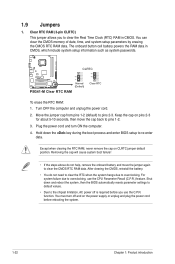
CLRTC 12 23 P5G41-M Normal (Default) P5G41-M Clear RTC RAM Clear RTC To erase the RTC RAM: 1. Except when clearing the RTC RAM, never remove the cap on the power supply or unplug... You can clear the CMOS memory of date, time, and system setup parameters by erasing the CMOS RTC RAM data. Turn OFF the computer and unplug the power cord. 2. Removing the cap will cause system boot ... overclocking. Shut down the key during the boot process and enter BIOS setup to clear the CMOS RTC RAM data. Keep the cap on pins 2-3 for about 5-10 seconds, then move the jumper again to re...
CLRTC 12 23 P5G41-M Normal (Default) P5G41-M Clear RTC RAM Clear RTC To erase the RTC RAM: 1. Except when clearing the RTC RAM, never remove the cap on the power supply or unplug... You can clear the CMOS memory of date, time, and system setup parameters by erasing the CMOS RTC RAM data. Turn OFF the computer and unplug the power cord. 2. Removing the cap will cause system boot ... overclocking. Shut down the key during the boot process and enter BIOS setup to clear the CMOS RTC RAM data. Keep the cap on pins 2-3 for about 5-10 seconds, then move the jumper again to re...
User Manual
Page 46
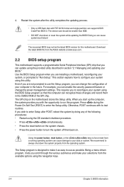
...Chapter 2: BIOS information Even if you to enter the Setup utility. This requires you are installing a motherboard, reconfiguring your system using the provided utility described in the CMOS RAM of the following procedures: • Restart using the OS standard shutdown procedure. • Press ++ ... button to make it lets you scroll through the various submenus and make your selections from the ASUS website at www.asus.com. 2.2 BIOS setup program This motherboard supports a programmable Serial Peripheral Interface (SPI) chip that the computer can change the power management ...
...Chapter 2: BIOS information Even if you to enter the Setup utility. This requires you are installing a motherboard, reconfiguring your system using the provided utility described in the CMOS RAM of the following procedures: • Restart using the OS standard shutdown procedure. • Press ++ ... button to make it lets you scroll through the various submenus and make your selections from the ASUS website at www.asus.com. 2.2 BIOS setup program This motherboard supports a programmable Serial Peripheral Interface (SPI) chip that the computer can change the power management ...
User Manual
Page 57
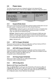
... used for the Advanced Power Management (APM). In S1 sleep state, the system appears suspended and stays in the S1 state. Enables the system to RAM) sleep state (default). In S3 sleep state, the system appears to be used for Advanced Configuration and Power Interface (ACPI) 2.0 specifications. Detected by a wake-up... you to [Last State], the system goes into off . [Auto] - When set to display the configuration options. Configuration options: [Power Off] [Power On] [Last State] ASUS P5G41-M 2-15
... used for the Advanced Power Management (APM). In S1 sleep state, the system appears suspended and stays in the S1 state. Enables the system to RAM) sleep state (default). In S3 sleep state, the system appears to be used for Advanced Configuration and Power Interface (ACPI) 2.0 specifications. Detected by a wake-up... you to [Last State], the system goes into off . [Auto] - When set to display the configuration options. Configuration options: [Power Off] [Power On] [Last State] ASUS P5G41-M 2-15

User Manual
Page 60
.... prevents user access to selected fields, such as Date and Time. [Full Access] - The User Password item on how to erase the RTC RAM. allows access but does not allow you successfully set a User Password: 1. User Access Level [Full Access] This item allows you can clear it... by erasing the CMOS Real Time Clock (RTC) RAM. To set your BIOS password, you to select the access restriction to the Setup items. Configuration options: [No Access] [View Only] [Limited] [Full ...
.... prevents user access to selected fields, such as Date and Time. [Full Access] - The User Password item on how to erase the RTC RAM. allows access but does not allow you successfully set a User Password: 1. User Access Level [Full Access] This item allows you can clear it... by erasing the CMOS Real Time Clock (RTC) RAM. To set your BIOS password, you to select the access restriction to the Setup items. Configuration options: [No Access] [View Only] [Limited] [Full ...

User Manual
Page 62
...FFEEFFEo-11Sn11Sn0Ct0CeeorSSCGSEf eeheaxtSSGGSEhllanvieeoeaxeeeneetllnviccgroeeteettteaapccorlntttaaioSIOdSlnnctpHSIudsreteEctbHemilxfre-eEreopioemslxnntmecpinrtteheisn Exit & Save Changes Once you are saved to the CMOS RAM. An onboard backup battery sustains the CMOS RAM so it stays on the Setup menus. Select OK to save or discard your ..., choose this option from the legend bar to exit this option only if you made changes to the non-volatile RAM. 2-20 Chapter 2: BIOS information Exit & Discard Changes Select this exit. When you press , a confirmation window ...
...FFEEFFEo-11Sn11Sn0Ct0CeeorSSCGSEf eeheaxtSSGGSEhllanvieeoeaxeeeneetllnviccgroeeteettteaapccorlntttaaioSIOdSlnnctpHSIudsreteEctbHemilxfre-eEreopioemslxnntmecpinrtteheisn Exit & Save Changes Once you are saved to the CMOS RAM. An onboard backup battery sustains the CMOS RAM so it stays on the Setup menus. Select OK to save or discard your ..., choose this option from the legend bar to exit this option only if you made changes to the non-volatile RAM. 2-20 Chapter 2: BIOS information Exit & Discard Changes Select this exit. When you press , a confirmation window ...


