User Manual
Page 3
Contents Notices vi Safety information vii About this guide viii Typography ix NCL-DE specifications summary x Chapter 1: Product introduction 1.1 Welcome 1-1 1.2 Package contents 1-1 1.3 Special features 1-2 1.3.1 Product highlights 1-2 1.3.2 Innovative ASUS features 1-4 Chapter 2: Hardware information 2.1 Before you proceed 2-1 2.2 Motherboard overview 2-2 2.2.1 Placement direction 2-2 2.2.2 Screw holes 2-2 2.2.3 Support kits for the motherboard 2-3 2.2.4 Motherboard layouts 2-6 2.2.5 Layout contents 2-8 2.3 Central Processing Unit...
Contents Notices vi Safety information vii About this guide viii Typography ix NCL-DE specifications summary x Chapter 1: Product introduction 1.1 Welcome 1-1 1.2 Package contents 1-1 1.3 Special features 1-2 1.3.1 Product highlights 1-2 1.3.2 Innovative ASUS features 1-4 Chapter 2: Hardware information 2.1 Before you proceed 2-1 2.2 Motherboard overview 2-2 2.2.1 Placement direction 2-2 2.2.2 Screw holes 2-2 2.2.3 Support kits for the motherboard 2-3 2.2.4 Motherboard layouts 2-6 2.2.5 Layout contents 2-8 2.3 Central Processing Unit...
User Manual
Page 5
... 5-21 5.2.6 Deleting a RAID configuration 5-24 5.2.7 Selecting the boot drive from a RAID set 5-25 5.2.8 Enabling the WriteCache 5-26 5.3 Global Array Manager 5-26 5.4 Adaptec SCSISelect(TM) Utility! (NCL-DE/SCSI model only 5-27 5.4.1 Configuring the SCSI controller 5-28 5.4.2 Enabling the HostRAID controller 5-28 5.4.3 Creating a RAID 0 set (Stripe 5-29 5.4.4 Creating a RAID 1 set (Mirror 5-33...
... 5-21 5.2.6 Deleting a RAID configuration 5-24 5.2.7 Selecting the boot drive from a RAID set 5-25 5.2.8 Enabling the WriteCache 5-26 5.3 Global Array Manager 5-26 5.4 Adaptec SCSISelect(TM) Utility! (NCL-DE/SCSI model only 5-27 5.4.1 Configuring the SCSI controller 5-28 5.4.2 Enabling the HostRAID controller 5-28 5.4.3 Creating a RAID 0 set (Stripe 5-29 5.4.4 Creating a RAID 1 set (Mirror 5-33...
User Manual
Page 6
... and utilities installation 6-15 6.4.1 Running the support CD 6-15 6.4.2 Drivers menu 6-15 6.4.3 Management Software menu 6-16 6.4.4 Utilities menu 6-16 6.4.5 Contact information 6-16 Appendix: Block diagrams A.1 NCL-DE/SCSI block diagram A-1 A.2 NCL-DE/1U block diagram A-2 vi
... and utilities installation 6-15 6.4.1 Running the support CD 6-15 6.4.2 Drivers menu 6-15 6.4.3 Management Software menu 6-16 6.4.4 Utilities menu 6-16 6.4.5 Contact information 6-16 Appendix: Block diagrams A.1 NCL-DE/SCSI block diagram A-1 A.2 NCL-DE/1U block diagram A-2 vi
User Manual
Page 11
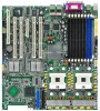
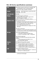
... BCM5721 Gigabit LAN controller Complies with PCI Express 1.0a specifications LAN 2: Broadcom BCM5721 Gigabit LAN controller Complies with Host RAID 0/1/0+1 - NCL-DE Series specifications summary CPU Chipset Front Side Bus Memory Expansion slots Storage Graphics LAN USB Dual 604-pin sockets for Intel®..., PCI Express 1.0a) 1 x mini-PCI socket for 2 additional ports) (continued on the rear panel, 1 connector at mid-board for ASUS® Server Management Board Intel® ICH5R Southbridge supports: - 4 x Ultra DMA 100/66/33 hard disk drives - 2 x SATA-150 with RAID 0, RAID ...
... BCM5721 Gigabit LAN controller Complies with PCI Express 1.0a specifications LAN 2: Broadcom BCM5721 Gigabit LAN controller Complies with Host RAID 0/1/0+1 - NCL-DE Series specifications summary CPU Chipset Front Side Bus Memory Expansion slots Storage Graphics LAN USB Dual 604-pin sockets for Intel®..., PCI Express 1.0a) 1 x mini-PCI socket for 2 additional ports) (continued on the rear panel, 1 connector at mid-board for ASUS® Server Management Board Intel® ICH5R Southbridge supports: - 4 x Ultra DMA 100/66/33 hard disk drives - 2 x SATA-150 with RAID 0, RAID ...
User Manual
Page 12
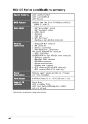
... Factor Support CD contents ASUS Smart Fan Control ASUS CrashFree BIOS 2 ASUS MyLogo2 AMI BIOS, 8 Mb FWH, Green, PnP, DMI2.0a, ACPI 2.0a SMBIOS 2.3, WfM2.0 1 x PS/2 keyboard port (purple) 1 x PS/2 mouse port (green) 2 x USB 2.0 ports 1 x Serial port 1 x VGA port 2 x LAN (RJ-45) ports 1 x Parallel port (NCL-DE/SCSI model only)...SCSI model only) 1 x BMC connector (NCL-DE/1U model only) SSI power supply (with 24-pin and 8-pin 12V plugs) ATX 12V 2.0 compliant E-ATX form factor: 12 in x 13 in (30.5 cm x 33 cm) Device drivers ASUS Live Update Utility ASUS Server Web-based Management (ASWM) Anti-virus...
... Factor Support CD contents ASUS Smart Fan Control ASUS CrashFree BIOS 2 ASUS MyLogo2 AMI BIOS, 8 Mb FWH, Green, PnP, DMI2.0a, ACPI 2.0a SMBIOS 2.3, WfM2.0 1 x PS/2 keyboard port (purple) 1 x PS/2 mouse port (green) 2 x USB 2.0 ports 1 x Serial port 1 x VGA port 2 x LAN (RJ-45) ports 1 x Parallel port (NCL-DE/SCSI model only)...SCSI model only) 1 x BMC connector (NCL-DE/1U model only) SSI power supply (with 24-pin and 8-pin 12V plugs) ATX 12V 2.0 compliant E-ATX form factor: 12 in x 13 in (30.5 cm x 33 cm) Device drivers ASUS Live Update Utility ASUS Server Web-based Management (ASWM) Anti-virus...

User Manual
Page 15
...above items is damaged or missing, contact your motherboard package for the following items. Motherboard ASUS NCL-DE Series motherboard Cables 2 x Serial ATA signal cables 1 x Serial ATA power cable (dual-plug) 2 x SCSI Ultra320 cable (NCL-DE/SCSI model only) 80-conductor IDE cable 3-in your package with the list below.... 1.2 Package contents Check your retailer. ASUS NCL-DE Series 1-1 The motherboard delivers a host of new features and latest technologies, making it , check the items in -1 floppy disk drive...
...above items is damaged or missing, contact your motherboard package for the following items. Motherboard ASUS NCL-DE Series motherboard Cables 2 x Serial ATA signal cables 1 x Serial ATA power cable (dual-plug) 2 x SCSI Ultra320 cable (NCL-DE/SCSI model only) 80-conductor IDE cable 3-in your package with the list below.... 1.2 Package contents Check your retailer. ASUS NCL-DE Series 1-1 The motherboard delivers a host of new features and latest technologies, making it , check the items in -1 floppy disk drive...
User Manual
Page 16
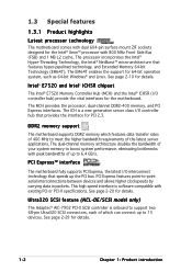
... higher bandwidth requirements of which can connect up to support two 68-pin Ultra320 SCSI connectors, each of the latest server applications. Ultra320 SCSI feature (NCL-DE/SCSI model only) The Adaptec® AIC-7902 PCI-X SCSI controller is onboard to 15 devices. The dual-channel memory architecture doubles the bandwidth...
... higher bandwidth requirements of which can connect up to support two 68-pin Ultra320 SCSI connectors, each of the latest server applications. Ultra320 SCSI feature (NCL-DE/SCSI model only) The Adaptec® AIC-7902 PCI-X SCSI controller is onboard to 15 devices. The dual-channel memory architecture doubles the bandwidth...
User Manual
Page 17
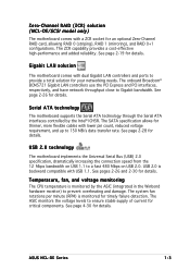
...an optional Zero-Channel RAID card, allowing RAID 0 (striping), RAID 1 (mirroring), and RAID 0+1 configurations. Zero-Channel RAID (ZCR) solution (NCL-DE/SCSI model only) The motherboard comes with a ZCR socket for timely failure detection. The SATA specification allows for details. USB 2.0 is ... The CPU temperature is backward compatible with lower pin count, reduced voltage requirement, and up to provide a total solution for details. ASUS NCL-DE Series 1-3 See page 2-26 for thinner, more flexible cables with USB 1.1. See page 2-28 for details. Serial ATA technology...
...an optional Zero-Channel RAID card, allowing RAID 0 (striping), RAID 1 (mirroring), and RAID 0+1 configurations. Zero-Channel RAID (ZCR) solution (NCL-DE/SCSI model only) The motherboard comes with a ZCR socket for timely failure detection. The SATA specification allows for details. USB 2.0 is ... The CPU temperature is backward compatible with lower pin count, reduced voltage requirement, and up to provide a total solution for details. ASUS NCL-DE Series 1-3 See page 2-26 for thinner, more flexible cables with USB 1.1. See page 2-28 for details. Serial ATA technology...
User Manual
Page 20
Chapter summary 2 2.1 Before you proceed 2-1 2.2 Motherboard overview 2-2 2.3 Central Processing Unit (CPU 2-10 2.4 System memory 2-14 2.5 Expansion slots 2-17 2.6 Jumpers 2-21 2.7 Connectors 2-26 ASUS NCL-DE Series
Chapter summary 2 2.1 Before you proceed 2-1 2.2 Motherboard overview 2-2 2.3 Central Processing Unit (CPU 2-10 2.4 System memory 2-14 2.5 Expansion slots 2-17 2.6 Jumpers 2-21 2.7 Connectors 2-26 ASUS NCL-DE Series

User Manual
Page 21
... component. • Before you install or remove any component, ensure that the system is switched off mode. NCL-DE Series ® SB_PWR1 ON Standby Power OFF Powered Off NCL-DE Series Standby power LED ASUS NCL-DE Series 2-1 The illustration below shows the location of the following precautions before you install motherboard components or...
... component. • Before you install or remove any component, ensure that the system is switched off mode. NCL-DE Series ® SB_PWR1 ON Standby Power OFF Powered Off NCL-DE Series Standby power LED ASUS NCL-DE Series 2-1 The illustration below shows the location of the following precautions before you install motherboard components or...
User Manual
Page 22
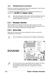
...motherboard components! 2.2.1 Placement direction When installing the motherboard, make sure that you place it into the chassis in the correct orientation. NCL-DE Series ® Place this side towards the rear of the chassis The SCSI connectors, Zero Channel RAID (ZCR) slot, ... grayed out in an S S I E E B 3 . 5 c o m p l i a n t c h a s s i s. Failure to ensure that the motherboard fits into it. These items are for NCL-DE/SCSI model only. 2.2 Motherboard overview Before you install the motherboard, study the configuration of your chassis to do so can damage the motherboard.
...motherboard components! 2.2.1 Placement direction When installing the motherboard, make sure that you place it into the chassis in the correct orientation. NCL-DE Series ® Place this side towards the rear of the chassis The SCSI connectors, Zero Channel RAID (ZCR) slot, ... grayed out in an S S I E E B 3 . 5 c o m p l i a n t c h a s s i s. Failure to ensure that the motherboard fits into it. These items are for NCL-DE/SCSI model only. 2.2 Motherboard overview Before you install the motherboard, study the configuration of your chassis to do so can damage the motherboard.
User Manual
Page 23
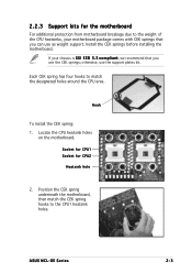
... match the CEK spring hooks to match the designated holes around the CPU area. 2.2.3 Support kits for CPU2 Heatsink hole 2. otherwise, use as weight support. ASUS NCL-DE Series 2-3 Locate the CPU heatsink holes on the motherboard. Hook To install the CEK spring: 1. Install the CEK springs before installing the motherboard.
... match the CEK spring hooks to match the designated holes around the CPU area. 2.2.3 Support kits for CPU2 Heatsink hole 2. otherwise, use as weight support. ASUS NCL-DE Series 2-3 Locate the CPU heatsink holes on the motherboard. Hook To install the CEK spring: 1. Install the CEK springs before installing the motherboard.
User Manual
Page 25
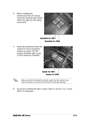
Standoffs for CPU1 Standoffs for illustration. otherwise, you can not install the CPU heatsinks properly. 8. ASUS NCL-DE Series 2-5 The CPU sockets should match the eight (8) CEK spring screw holes. Socket for CPU1 Socket for CPU2 Make sure that should be right ...
Standoffs for CPU1 Standoffs for illustration. otherwise, you can not install the CPU heatsinks properly. 8. ASUS NCL-DE Series 2-5 The CPU sockets should match the eight (8) CEK spring screw holes. Socket for CPU1 Socket for CPU2 Make sure that should be right ...
User Manual
Page 28
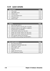
... 2-8 Chapter 2: Hardware information Mini-PCI socket Jumpers 1. Gigabit LAN controller setting (3-pin LAN1_EN1) 7. Zero-Channel RAID socket 5. SCSI controller setting (3-pin SCSI_EN1) 9. Parallel port (for NCL-DE model only) 3. Gigabit LAN (RJ-45) ports 7. Serial (COM1) port 5. PCI/PCI-X slots 4. 2.2.5 Layout contents Slots/Sockets 1.
... 2-8 Chapter 2: Hardware information Mini-PCI socket Jumpers 1. Gigabit LAN controller setting (3-pin LAN1_EN1) 7. Zero-Channel RAID socket 5. SCSI controller setting (3-pin SCSI_EN1) 9. Parallel port (for NCL-DE model only) 3. Gigabit LAN (RJ-45) ports 7. Serial (COM1) port 5. PCI/PCI-X slots 4. 2.2.5 Layout contents Slots/Sockets 1.
User Manual
Page 30
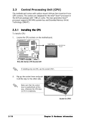
... fit in the 604-pin package with surface mount 604-pin Zero Insertion Force (ZIF) sockets. CPU1 Intel Xeon CPU2 Gold Arrow Pin A1 NCL-DE Series ® NCL-DE Series CPU Socket 604 If installing only one CPU, use the socket CPU1. 2. Make sure that the socket lever is pushed back...
... fit in the 604-pin package with surface mount 604-pin Zero Insertion Force (ZIF) sockets. CPU1 Intel Xeon CPU2 Gold Arrow Pin A1 NCL-DE Series ® NCL-DE Series CPU Socket 604 If installing only one CPU, use the socket CPU1. 2. Make sure that the socket lever is pushed back...
User Manual
Page 31
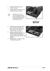
3. DO NOT force the CPU into the socket until it is locked. 6. Marked corner (gold arrow) ASUS NCL-DE Series 2-11 This thermal grease should come with the CPU package. 7. Repeat steps 1 to 6 if you wish to prevent bending the pins and damaging ...
3. DO NOT force the CPU into the socket until it is locked. 6. Marked corner (gold arrow) ASUS NCL-DE Series 2-11 This thermal grease should come with the CPU package. 7. Repeat steps 1 to 6 if you wish to prevent bending the pins and damaging ...
User Manual
Page 33
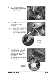
Use a Phillips screwdriver to connect the CPU fan connector! The heatsinks appear as shown when installed. Do not forget to tighten the four heatsink screws in a diagonal sequence. 3. CPU_FAN2 connector ASUS NCL-DE Series CPU_FAN1 connector 2-13 Hardware monitoring errors may occur if you have installed a second CPU, then connect the fan cable to the 4-pin connector labeled CPU_FAN2. Connect the fan cable to plug this connector. 4. 2. Repeat steps 1 to 3 to install the other heatsink if you fail to the 4-pin connector labeled CPU_FAN1.
Use a Phillips screwdriver to connect the CPU fan connector! The heatsinks appear as shown when installed. Do not forget to tighten the four heatsink screws in a diagonal sequence. 3. CPU_FAN2 connector ASUS NCL-DE Series CPU_FAN1 connector 2-13 Hardware monitoring errors may occur if you have installed a second CPU, then connect the fan cable to the 4-pin connector labeled CPU_FAN2. Connect the fan cable to plug this connector. 4. 2. Repeat steps 1 to 3 to install the other heatsink if you fail to the 4-pin connector labeled CPU_FAN1.
User Manual
Page 34
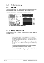
The figure illustrates the location of the DDR2 DIMM sockets: NCL-DE Series ® 128 Pins NCL-DE Series 240-pin DDR2 DIMM sockets 112 Pins DIMM_B4 DIMM_A4 DIMM_B3 DIMM_A3 DIMM_B2 DIMM_A2 DIMM_B1 DIMM_A1 2.4.2 Memory configurations You may detect less than 16 ... only one memory module, install into any other socket would not work. 2-14 Chapter 2: Hardware information Refer to the DDR2 Qualified Vendors List at the ASUS web site. • Due to chipset resource allocation, the system may install 256 MB, 512 MB and 1 GB registered ECC DDR2 DIMMs into the DIMM...
The figure illustrates the location of the DDR2 DIMM sockets: NCL-DE Series ® 128 Pins NCL-DE Series 240-pin DDR2 DIMM sockets 112 Pins DIMM_B4 DIMM_A4 DIMM_B3 DIMM_A3 DIMM_B2 DIMM_A2 DIMM_B1 DIMM_A1 2.4.2 Memory configurations You may detect less than 16 ... only one memory module, install into any other socket would not work. 2-14 Chapter 2: Hardware information Refer to the DDR2 Qualified Vendors List at the ASUS web site. • Due to chipset resource allocation, the system may install 256 MB, 512 MB and 1 GB registered ECC DDR2 DIMMs into the DIMM...
User Manual
Page 35
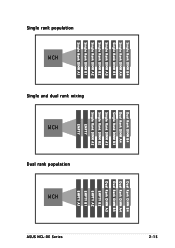
Single rank population MCH Single and dual rank mixing MCH Dual rank population MCH ASUS NCL-DE Series Single Rank DIMM B4 Single Rank DIMM A4 Single Rank DIMM B3 Single Rank DIMM A3 Single Rank DIMM B2 Single Rank DIMM A2 Single Rank DIMM B1 Single Rank DIMM A1 Dual Rank DIMM B4 Dual Rank DIMM A4 Single Rank DIMM B3 Single Rank DIMM A3 Single Rank DIMM B2 Single Rank DIMM A2 EMPTY EMPTY Dual Rank DIMM B4 Dual Rank DIMM A4 Dual Rank DIMM B3 Dual Rank DIMM A3 EMPTY B2 EMPTY A2 EMPTY B1 EMPTY A1 2-15
Single rank population MCH Single and dual rank mixing MCH Dual rank population MCH ASUS NCL-DE Series Single Rank DIMM B4 Single Rank DIMM A4 Single Rank DIMM B3 Single Rank DIMM A3 Single Rank DIMM B2 Single Rank DIMM A2 Single Rank DIMM B1 Single Rank DIMM A1 Dual Rank DIMM B4 Dual Rank DIMM A4 Single Rank DIMM B3 Single Rank DIMM A3 Single Rank DIMM B2 Single Rank DIMM A2 EMPTY EMPTY Dual Rank DIMM B4 Dual Rank DIMM A4 Dual Rank DIMM B3 Dual Rank DIMM A3 EMPTY B2 EMPTY A2 EMPTY B1 EMPTY A1 2-15
User Manual
Page 37
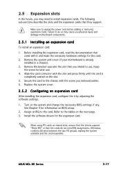
Failure to do not need to use . 4. Remove the bracket opposite the slot that they support. Refer to the card. ASUS NCL-DE Series 2-17 Assign an IRQ to the tables on the next page. 3. Align the card connector with the screw you intend to install expansion ...
Failure to do not need to use . 4. Remove the bracket opposite the slot that they support. Refer to the card. ASUS NCL-DE Series 2-17 Assign an IRQ to the tables on the next page. 3. Align the card connector with the screw you intend to install expansion ...