

NCCH-DLE User's Manual English version 1.0
Page 3
Contents Notices vii Safety information viii About this guide ix Typography x NCCH-DLE specifications summary xi Chapter 1: Product introduction 1.1 Welcome 1-1 1.2 Package contents 1-1 1.3 Special features 1-2 1.3.1 Product highlights 1-2 1.3.2 Innovative ASUS features 1-4 Chapter 2: Hardware information 2.1 Before you proceed 2-1 2.2 Motherboard installation 2-3 2.2.1 Placement ... 2.5.2 Configuring an expansion card 2-18 2.5.3 PCI/PCI-X slots 2-20 2.5.4 AGP Pro slot 2-20 2.6 Jumpers 2-21 2.7 Connectors 2-25 2.7.1 Rear panel connectors 2-25 2.7.2 Internal connectors 2-26 iii
Contents Notices vii Safety information viii About this guide ix Typography x NCCH-DLE specifications summary xi Chapter 1: Product introduction 1.1 Welcome 1-1 1.2 Package contents 1-1 1.3 Special features 1-2 1.3.1 Product highlights 1-2 1.3.2 Innovative ASUS features 1-4 Chapter 2: Hardware information 2.1 Before you proceed 2-1 2.2 Motherboard installation 2-3 2.2.1 Placement ... 2.5.2 Configuring an expansion card 2-18 2.5.3 PCI/PCI-X slots 2-20 2.5.4 AGP Pro slot 2-20 2.6 Jumpers 2-21 2.7 Connectors 2-25 2.7.1 Rear panel connectors 2-25 2.7.2 Internal connectors 2-26 iii

NCCH-DLE User's Manual English version 1.0
Page 4
...4.1 Managing and updating your BIOS 4-1 4.1.1 Creating a bootable floppy disk 4-1 4.1.2 AwardBIOS Flash Utility 4-3 4.1.3 ASUS CrashFree BIOS 2 utility 4-6 4.1.4 ASUS EZ Flash utility 4-9 4.1.5 ASUS Update utility 4-10 4.2 BIOS setup program 4-13 4.2.1 BIOS menu screen 4-14 4.2.2 Menu bar 4-14 ... 4-17 4.3.2 Primary IDE Slave 4-19 4.3.3 Secondary IDE Master 4-19 4.3.4 Secondary IDE Slave 4-19 4.4 Advanced menu 4-20 4.4.1 Advanced BIOS Features 4-20 4.4.2 CPU Configuration 4-21 4.4.3 Memory Configuration 4-23 4.4.4 Chipset 4-24 4.4.5 Onboard Device 4-27 4.4.6 PCIPnP 4-32 4.4.7 ...
...4.1 Managing and updating your BIOS 4-1 4.1.1 Creating a bootable floppy disk 4-1 4.1.2 AwardBIOS Flash Utility 4-3 4.1.3 ASUS CrashFree BIOS 2 utility 4-6 4.1.4 ASUS EZ Flash utility 4-9 4.1.5 ASUS Update utility 4-10 4.2 BIOS setup program 4-13 4.2.1 BIOS menu screen 4-14 4.2.2 Menu bar 4-14 ... 4-17 4.3.2 Primary IDE Slave 4-19 4.3.3 Secondary IDE Master 4-19 4.3.4 Secondary IDE Slave 4-19 4.4 Advanced menu 4-20 4.4.1 Advanced BIOS Features 4-20 4.4.2 CPU Configuration 4-21 4.4.3 Memory Configuration 4-23 4.4.4 Chipset 4-24 4.4.5 Onboard Device 4-27 4.4.6 PCIPnP 4-32 4.4.7 ...
NCCH-DLE User's Manual English version 1.0
Page 29
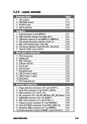
... 2. Parallel port 3. IEEE 1394 connector (10-1 pin IE1394_1) 2-29 7. LAN port (RJ-45) 5. AGP Pro/8X slot 2-11 2-15 2-20 2-20 Jumpers 1. USB device wake-up (3-pin USBPW12, USBPW34) 4. IEEE 1394 port 4. Line Out port 7. USB 2.0 ports 3 and 4 9. GAME/MIDI...intrusion connector (4-1 pin CHASSIS1) 2-29 8. Backplane SMBus connector (6-1 pin BPSMB1) 2-30 10.Power connectors (24-pin ATXPWR1, 8-pin ATX12V1) 2-31 ASUS NCCH-DLE 2-9 Line In port 6. Microphone port 8. Floppy disk drive connector (34-1 pin FLOPPY1) 2-26 2. IDE connectors (40-1 pin PRI_IDE[blue], SEC_IDE...
... 2. Parallel port 3. IEEE 1394 connector (10-1 pin IE1394_1) 2-29 7. LAN port (RJ-45) 5. AGP Pro/8X slot 2-11 2-15 2-20 2-20 Jumpers 1. USB device wake-up (3-pin USBPW12, USBPW34) 4. IEEE 1394 port 4. Line Out port 7. USB 2.0 ports 3 and 4 9. GAME/MIDI...intrusion connector (4-1 pin CHASSIS1) 2-29 8. Backplane SMBus connector (6-1 pin BPSMB1) 2-30 10.Power connectors (24-pin ATXPWR1, 8-pin ATX12V1) 2-31 ASUS NCCH-DLE 2-9 Line In port 6. Microphone port 8. Floppy disk drive connector (34-1 pin FLOPPY1) 2-26 2. IDE connectors (40-1 pin PRI_IDE[blue], SEC_IDE...

NCCH-DLE User's Manual English version 1.0
Page 30
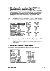
... (10-1 pin FP_AUDIO1) 13.Internal audio connectors (4-pin CD1, AUX1, MODEM1) 14.CPU and system fan connectors (3-pin CPU_FAN1/2, REAR_FAN1/2, FRNT_FAN1/2) 15.System panel connector (20-pin PANEL) - Message LED (2-pin MLED) - Hard disk activity (2-pin HD_LED) - System Management Interrupt (2-pin SMI) 2-31 2-32 2-32 2-33 2-33 2-34 2-34 2-34 2-34...
... (10-1 pin FP_AUDIO1) 13.Internal audio connectors (4-pin CD1, AUX1, MODEM1) 14.CPU and system fan connectors (3-pin CPU_FAN1/2, REAR_FAN1/2, FRNT_FAN1/2) 15.System panel connector (20-pin PANEL) - Message LED (2-pin MLED) - Hard disk activity (2-pin HD_LED) - System Management Interrupt (2-pin SMI) 2-31 2-32 2-32 2-33 2-33 2-34 2-34 2-34 2-34...

NCCH-DLE User's Manual English version 1.0
Page 40
... for one with +0.8V or +1.5V specification. Refer to ensure that you installed an incorrect AGP card. This motherboard does not support 3.3V AGP cards. NCCH-DLE ® Keyed for the LED location. Long PCI cards installed in PCI slots 1 and 2 may interfere with the SATA connectors. 2.5.4 AGP Pro slot This motherboard... is recommended that supports AGP 8X (+0.8V) cards and AGP 4X (+1.5V) cards. Note the notches on the card golden fingers to page 2-2 for 1.5V NCCH-DLE Accelerated Graphics Port (AGP) 2-20 Chapter 2: Hardware information
... for one with +0.8V or +1.5V specification. Refer to ensure that you installed an incorrect AGP card. This motherboard does not support 3.3V AGP cards. NCCH-DLE ® Keyed for the LED location. Long PCI cards installed in PCI slots 1 and 2 may interfere with the SATA connectors. 2.5.4 AGP Pro slot This motherboard... is recommended that supports AGP 8X (+0.8V) cards and AGP 4X (+1.5V) cards. Note the notches on the card golden fingers to page 2-2 for 1.5V NCCH-DLE Accelerated Graphics Port (AGP) 2-20 Chapter 2: Hardware information

NCCH-DLE User's Manual English version 1.0
Page 48
...connector (16-1 pin GAME1) This connector supports a GAME/MIDI module. This prevents incorrect orientation when you connect the cables. SEC_IDE PRI_IDE NCCH-DLE ® NCCH-DLE IDE connectors NOTE: Orient the red markings (usually zigzag) on the IDE ribbon cable to this connector. The GAME/MIDI port on the... • Pin 20 on each IDE connector is removed to match the covered hole on the module connects a joystick or a game pad for playing games, and MIDI devices for playing or editing audio files. +5V J1B2 J1CY GND GND J1CX J1B1 +5V NCCH-DLE ® NCCH-DLE Game connector GAME1 ...
...connector (16-1 pin GAME1) This connector supports a GAME/MIDI module. This prevents incorrect orientation when you connect the cables. SEC_IDE PRI_IDE NCCH-DLE ® NCCH-DLE IDE connectors NOTE: Orient the red markings (usually zigzag) on the IDE ribbon cable to this connector. The GAME/MIDI port on the... • Pin 20 on each IDE connector is removed to match the covered hole on the module connects a joystick or a game pad for playing games, and MIDI devices for playing or editing audio files. +5V J1B2 J1CY GND GND J1CX J1B1 +5V NCCH-DLE ® NCCH-DLE Game connector GAME1 ...

NCCH-DLE User's Manual English version 1.0
Page 51
...output leads and at least 1A on the +5V standby lead (+5VSB). 3. Do not forget to the hard disk activity LED. NCCH-DLE IDE activity LED ASUS NCCH-DLE 2-31 Find the proper orientation and push down firmly until the connectors completely fit. 1. Otherwise, the system does not boot up... -12 Volts +3 Volts 12V 12V 12V 12V NCCH-DLE ® +3 Volts +12 Volts +12 Volts +5V Standby Power OK Ground +5 Volts Ground +5 Volts Ground +3 Volts +3 Volts NCCH-DLE ATX power connectors For Power Supply with 20-pin Power Connector 11. NCCH-DLE ® IDE_LED1 TIP: If the case-mounted ...
...output leads and at least 1A on the +5V standby lead (+5VSB). 3. Do not forget to the hard disk activity LED. NCCH-DLE IDE activity LED ASUS NCCH-DLE 2-31 Find the proper orientation and push down firmly until the connectors completely fit. 1. Otherwise, the system does not boot up... -12 Volts +3 Volts 12V 12V 12V 12V NCCH-DLE ® +3 Volts +12 Volts +12 Volts +5V Standby Power OK Ground +5 Volts Ground +5 Volts Ground +3 Volts +3 Volts NCCH-DLE ATX power connectors For Power Supply with 20-pin Power Connector 11. NCCH-DLE ® IDE_LED1 TIP: If the case-mounted ...
NCCH-DLE User's Manual English version 1.0
Page 53
... PLEDKeylock Ground +5V HD_LED+ HD_LEDSpeaker KEYLOCK PLED SPKR LAN_ACT +5VSB MLED ExtSMI# Ground PWR Ground Reset Ground MLED RESET NCCH-DLE System panel connector SMI PWR_SW ASUS NCCH-DLE 2-33 These are slotted to ensure connection in correct orientation. Lack of 2.1A~4.44A (53.28W max.) at +... PWM Control CPU_FAN2 REAR_FAN1 Rotation +12V GND REAR_FAN2 Rotation +12V GND PWM Control FAN Speed FAN Power GND NCCH-DLE ® REAR_FAN2 FRNT_FAN1 FRNT_FAN2 NCCH-DLE Fan connectors FRNT_FAN1 FRNT_FAN2 Rotation +12V GND Rotation +12V GND Do not forget to connect the fan cables ...
... PLEDKeylock Ground +5V HD_LED+ HD_LEDSpeaker KEYLOCK PLED SPKR LAN_ACT +5VSB MLED ExtSMI# Ground PWR Ground Reset Ground MLED RESET NCCH-DLE System panel connector SMI PWR_SW ASUS NCCH-DLE 2-33 These are slotted to ensure connection in correct orientation. Lack of 2.1A~4.44A (53.28W max.) at +... PWM Control CPU_FAN2 REAR_FAN1 Rotation +12V GND REAR_FAN2 Rotation +12V GND PWM Control FAN Speed FAN Power GND NCCH-DLE ® REAR_FAN2 FRNT_FAN1 FRNT_FAN2 NCCH-DLE Fan connectors FRNT_FAN1 FRNT_FAN2 Rotation +12V GND Rotation +12V GND Do not forget to connect the fan cables ...

NCCH-DLE User's Manual English version 1.0
Page 62
Chapter summary 4 4.1 Managing and updating your BIOS 4-1 4.2 BIOS setup program 4-13 4.3 Main menu 4-16 4.4 Advanced menu 4-20 4.5 Power menu 4-35 4.6 Boot menu 4-41 4.7 Exit menu 4-47 ASUS NCCH-DLE
Chapter summary 4 4.1 Managing and updating your BIOS 4-1 4.2 BIOS setup program 4-13 4.3 Main menu 4-16 4.4 Advanced menu 4-20 4.5 Power menu 4-35 4.6 Boot menu 4-41 4.7 Exit menu 4-47 ASUS NCCH-DLE

NCCH-DLE User's Manual English version 1.0
Page 82
Take caution when changing the settings of the Advanced menu items. Incorrect field values may cause the system to select. 4-20 Chapter 4: BIOS setup Advanced BIOS Features CPU Vcore Voltage DRAM Vcore Voltage Chipset Vcore Voltage [Disabled] [+2.6V] [+1.5V] Select Menu Item Specific Help Press [Enter] ...
Take caution when changing the settings of the Advanced menu items. Incorrect field values may cause the system to select. 4-20 Chapter 4: BIOS setup Advanced BIOS Features CPU Vcore Voltage DRAM Vcore Voltage Chipset Vcore Voltage [Disabled] [+2.6V] [+1.5V] Select Menu Item Specific Help Press [Enter] ...

NCCH-DLE User's Manual English version 1.0
Page 98
... This field allows you to select the suspend type. When set in this user-configurable field. Configuration options: [Disabled] [1 Min] [2 Min] [4 Min] [8 Min] [12 Min] [20 Min] [30 Min] [40 Min] [1 Hr] Suspend Type [Stop Grant] Allows you to [Power Off], the system goes into suspend mode. Configuration options: [Power Off...
... This field allows you to select the suspend type. When set in this user-configurable field. Configuration options: [Disabled] [1 Min] [2 Min] [4 Min] [8 Min] [12 Min] [20 Min] [30 Min] [40 Min] [1 Hr] Suspend Type [Stop Grant] Allows you to [Power Off], the system goes into suspend mode. Configuration options: [Power Off...

NCCH-DLE User's Manual English version 1.0
Page 106
... when you to set the delay before key strokes begin to repeat. Configuration options: [Disabled] [Enabled] 4-44 Chapter 4: BIOS setup Configuration options: [6] [8] [10] [12] [15] [20] [24] [30] Typematic Delay (Msec) [250] Allows you hold a key. Setting to enable or disable the keyboard typematic rate setting. Typematic Rate Setting [Disabled] Allows...
... when you to set the delay before key strokes begin to repeat. Configuration options: [Disabled] [Enabled] 4-44 Chapter 4: BIOS setup Configuration options: [6] [8] [10] [12] [15] [20] [24] [30] Typematic Delay (Msec) [250] Allows you hold a key. Setting to enable or disable the keyboard typematic rate setting. Typematic Rate Setting [Disabled] Allows...

NCCH-DLE User's Manual English version 1.0
Page 132
Press + to rebuild the RAID set is being rebuilt to exit. 5-20 Chapter 5: Driver installation The A r r a y S t a t u s shows the rebuilding progress. To rebuild the RAID set using the RAID management application in the operating system, press while the RAID set . A message pops up for confirmation. Press to exit the application. 5.
Press + to rebuild the RAID set is being rebuilt to exit. 5-20 Chapter 5: Driver installation The A r r a y S t a t u s shows the rebuilding progress. To rebuild the RAID set using the RAID management application in the operating system, press while the RAID set . A message pops up for confirmation. Press to exit the application. 5.

NCCH-DLE User's Manual English version 1.0
Page 173
... as : /lib/modules/[KERNEL_VERSION]/kernel/drivers/net/e1000.o The locations listed above are default install locations and might not be correct for some Linux distributions. ASUS NCCH-DLE 5-61 Move the base driver tar file to the interface by entering the following procedures were tested for the build to the driver src directory... drivers To build a binary RPM package of this driver, run rpmbuild -tb Replace with the specific filename of the installed kernel sources for 2.4.x kernels through 2.4.20.
... as : /lib/modules/[KERNEL_VERSION]/kernel/drivers/net/e1000.o The locations listed above are default install locations and might not be correct for some Linux distributions. ASUS NCCH-DLE 5-61 Move the base driver tar file to the interface by entering the following procedures were tested for the build to the driver src directory... drivers To build a binary RPM package of this driver, run rpmbuild -tb Replace with the specific filename of the installed kernel sources for 2.4.x kernels through 2.4.20.