User Manual
Page 15
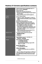
...set as a boot disk. Some hyper DIMMs only support one DIMM per channel. Maximus IV Extreme specifications summary CPU Chipset Memory Expansion Slots Multi-GPU Technology Storage LGA1155 socket for ...The Intel® Turbo Boost Technology 2.0 support depends on the CPU types. ** Refer to www.asus.com for the Memory QVL (Qualified Vendors Lists) 4 x PCIe2.0 x16 slots (single @x16, ...™ with DIMMs of individual CPUs. A RAID array over 2TB cannot be supported with NF200 / ATI ��C�r�o�ss�F��ir�e�X�™...
...set as a boot disk. Some hyper DIMMs only support one DIMM per channel. Maximus IV Extreme specifications summary CPU Chipset Memory Expansion Slots Multi-GPU Technology Storage LGA1155 socket for ...The Intel® Turbo Boost Technology 2.0 support depends on the CPU types. ** Refer to www.asus.com for the Memory QVL (Qualified Vendors Lists) 4 x PCIe2.0 x16 slots (single @x16, ...™ with DIMMs of individual CPUs. A RAID array over 2TB cannot be supported with NF200 / ATI ��C�r�o�ss�F��ir�e�X�™...

User Manual
Page 34
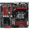
2.2 Motherboard overview 2.2.1 Motherboard layout NF200 Refer to 2.2.8 Connectors for more information about rear panel connectors and internal connectors. 2-2 Chapter 2: Hardware information
2.2 Motherboard overview 2.2.1 Motherboard layout NF200 Refer to 2.2.8 Connectors for more information about rear panel connectors and internal connectors. 2-2 Chapter 2: Hardware information

User Manual
Page 46
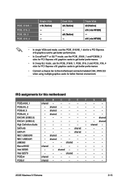
Failure to unplug the power cord before adding or removing expansion cards. 2.2.5 Expansion slots Ensure to do so may cause you physical injury and damage motherboard components. NF200 Slot No. Slot Description 1 PCIe 2.0 x16/8_1 slot 2 PCIe 2.0 x1_1 slot 3 PCIe 2.0 x16_2 slot 4 PCIe 2.0 x8_3 slot (PCIe 2.0 x16 slot with x8 bandwidth) 5 PCIe 2.0 x16_4 slot 6 PCIe 2.0 x4_1 slot 2-14 Chapter 2: Hardware information
Failure to unplug the power cord before adding or removing expansion cards. 2.2.5 Expansion slots Ensure to do so may cause you physical injury and damage motherboard components. NF200 Slot No. Slot Description 1 PCIe 2.0 x16/8_1 slot 2 PCIe 2.0 x1_1 slot 3 PCIe 2.0 x16_2 slot 4 PCIe 2.0 x8_3 slot (PCIe 2.0 x16 slot with x8 bandwidth) 5 PCIe 2.0 x16_4 slot 6 PCIe 2.0 x4_1 slot 2-14 Chapter 2: Hardware information
User Manual
Page 47
...F G H PCIEx16/8_1 shared - - - - - - - PCIEx16_4 - shared High Definition Audio - - - - - - shared - - - Marvell9182 shared - - - - - - - shared - - - - PCIEx16_2 - shared - shared - - - - - - Intel 82579 - - - ASUS Maximus IV Extreme 2-15 x16 (via NF200) - EHCI#0 (USB2.0) - - - - - - - SATA #0 - - - - Intel 82583 - - PCIEx4 shared - - - - - - - shared - - - - - - shared - - - JMB362 - - - PCIEx1 shared - - - - - - - NEC USB3.0#0 - shared - - - - - - shared...
...F G H PCIEx16/8_1 shared - - - - - - - PCIEx16_4 - shared High Definition Audio - - - - - - shared - - - Marvell9182 shared - - - - - - - shared - - - - PCIEx16_2 - shared - shared - - - - - - Intel 82579 - - - ASUS Maximus IV Extreme 2-15 x16 (via NF200) - EHCI#0 (USB2.0) - - - - - - - SATA #0 - - - - Intel 82583 - - PCIEx4 shared - - - - - - - shared - - - - - - shared - - - JMB362 - - - PCIEx1 shared - - - - - - - NEC USB3.0#0 - shared - - - - - - shared...

User Manual
Page 105
...Driving Voltage [Auto] Allows you to work stably under high voltage settings. The values range from 0.80825V to set the NF200 voltage. NF200 Voltage [Auto] Allows you to 1.70925V with a 0.01325V interval. • The values of the CPU Manual Voltage,... CPU Offset Voltage, DRAM Voltage, VCCSA Voltage, VCCIO Voltage, CPU PLL Voltage, PCH Voltage, and NF200 Voltage items are labelled in different color, indicating the risk levels of high voltage settings. • The system may .... PCH Voltage [Auto] Allows you to set the PCH PLL votage. ASUS Maximus IV Extreme 3-13
...Driving Voltage [Auto] Allows you to work stably under high voltage settings. The values range from 0.80825V to set the NF200 voltage. NF200 Voltage [Auto] Allows you to 1.70925V with a 0.01325V interval. • The values of the CPU Manual Voltage,... CPU Offset Voltage, DRAM Voltage, VCCSA Voltage, VCCIO Voltage, CPU PLL Voltage, PCH Voltage, and NF200 Voltage items are labelled in different color, indicating the risk levels of high voltage settings. • The system may .... PCH Voltage [Auto] Allows you to set the PCH PLL votage. ASUS Maximus IV Extreme 3-13
User Manual
Page 122
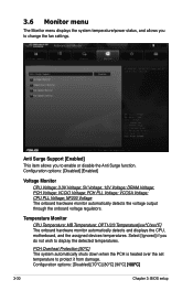
...ºC] The system automatically shuts down when the PCH is heated over the set temperature to display the detected temperatures. CPU PLL Voltage; VCCIO Voltage; NF200 Voltage The onboard hardware monitor automatically detects the voltage output through the onboard voltage regulators. MB Temperature; 3.6 Monitor menu The Monitor menu displays the system...
...ºC] The system automatically shuts down when the PCH is heated over the set temperature to display the detected temperatures. CPU PLL Voltage; VCCIO Voltage; NF200 Voltage The onboard hardware monitor automatically detects the voltage output through the onboard voltage regulators. MB Temperature; 3.6 Monitor menu The Monitor menu displays the system...