User Manual
Page 11
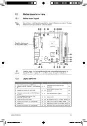
...8. Place four screws into the chassis in the correct orientation. System panel connector (10-1 pin F_PANEL) 1-15 14. DO NOT overtighten the screws! Clear RTC RAM (3-pin CLRTC) 1-9 4. 1.2 1.2.1 Motherboard overview Motherboard layout Ensure that you install the motherboard into the holes indicated by circles to secure the motherboard to the rear...CON1) 1-16 13. Serial ATA connectors (7-pin SATA1, SATA2) 1-13 6. USB connector (10-1 pin USB56, USB78) 1-13 7. Front panel audio connector (10-1 pin AAFP) 1-15 ASUS AT5NM10-I E5179_AT5NM10-I.indb 2 1-2 12/22/09 5:55:43 PM
...8. Place four screws into the chassis in the correct orientation. System panel connector (10-1 pin F_PANEL) 1-15 14. DO NOT overtighten the screws! Clear RTC RAM (3-pin CLRTC) 1-9 4. 1.2 1.2.1 Motherboard overview Motherboard layout Ensure that you install the motherboard into the holes indicated by circles to secure the motherboard to the rear...CON1) 1-16 13. Serial ATA connectors (7-pin SATA1, SATA2) 1-13 6. USB connector (10-1 pin USB56, USB78) 1-13 7. Front panel audio connector (10-1 pin AAFP) 1-15 ASUS AT5NM10-I E5179_AT5NM10-I.indb 2 1-2 12/22/09 5:55:43 PM
User Manual
Page 18
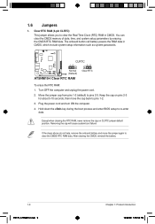
...-I.indb 9 Chapter 1: Product introduction 12/22/09 5:55:54 PM The onboard button cell battery powers the RAM data in CMOS. Plug the power cord and turn ON the computer. 4. 1.6 Jumpers 1. To erase the RTC RAM: 1. Hold down the key during the boot process and enter BIOS setup to pins 2-3. Clear RTC... remove the cap on pins 2-3 for about 5-10 seconds, then move the jumper again to clear the Real Time Clock (RTC) RAM in CMOS, which include system setup information such as system passwords. Move the jumper cap from pins 1-2 (default) to re-enter data. Turn OFF the ...
...-I.indb 9 Chapter 1: Product introduction 12/22/09 5:55:54 PM The onboard button cell battery powers the RAM data in CMOS. Plug the power cord and turn ON the computer. 4. 1.6 Jumpers 1. To erase the RTC RAM: 1. Hold down the key during the boot process and enter BIOS setup to pins 2-3. Clear RTC... remove the cap on pins 2-3 for about 5-10 seconds, then move the jumper again to clear the Real Time Clock (RTC) RAM in CMOS, which include system setup information such as system passwords. Move the jumper cap from pins 1-2 (default) to re-enter data. Turn OFF the ...

User Manual
Page 37
... Advanced Configuration and Power Interface (ACPI) state to Enabled, the ACPI APIC table pointer is included in the RSDT pointer list. Configuration options: [Disabled] [Enabled] ASUS AT5NM10-I E5179_AT5NM10-I.indb 10 2-10 12/22/09 5:56:17 PM 2.4.5 PCI PnP The PCI PnP menu items allow you to [No], BIOS configures all... and Power Interface (ACPI) support in the Application-Specific Integrated Circuit (ASIC). Configuration options: [No] [Yes] 2.5 Power menu The Power menu items allow you to RAM) sleep state (default).
... Advanced Configuration and Power Interface (ACPI) state to Enabled, the ACPI APIC table pointer is included in the RSDT pointer list. Configuration options: [Disabled] [Enabled] ASUS AT5NM10-I E5179_AT5NM10-I.indb 10 2-10 12/22/09 5:56:17 PM 2.4.5 PCI PnP The PCI PnP menu items allow you to [No], BIOS configures all... and Power Interface (ACPI) support in the Application-Specific Integrated Circuit (ASIC). Configuration options: [No] [Yes] 2.5 Power menu The Power menu items allow you to RAM) sleep state (default).

User Manual
Page 40
... to run Setup during POST. The message Password Installed appears after you can clear it by erasing the CMOS Real Time Clock (RTC) RAM. The message Password uninstalled appears. Change Supervisor Password Select this item shows Installed. The Supervisor Password item on how to six letters or ...Hit 'DEL' Message Display [Enabled] When set or change the supervisor password, follow the same steps in a password containing up to erase the RTC RAM. 2-13 E5179_AT5NM10-I.indb 13 Chapter 2: BIOS information 12/22/09 5:56:20 PM To set your password. See section 1.6 Jumpers for the F1...
... to run Setup during POST. The message Password Installed appears after you can clear it by erasing the CMOS Real Time Clock (RTC) RAM. The message Password uninstalled appears. Change Supervisor Password Select this item shows Installed. The Supervisor Password item on how to six letters or ...Hit 'DEL' Message Display [Enabled] When set or change the supervisor password, follow the same steps in a password containing up to erase the RTC RAM. 2-13 E5179_AT5NM10-I.indb 13 Chapter 2: BIOS information 12/22/09 5:56:20 PM To set your password. See section 1.6 Jumpers for the F1...


