
User Manual
Page 2
... inserting the board into a full-length AT compatible connector, and connecting a SCSI cable from the on the AHA-1540B/1542B. The following section details the preparation procedure for the Adaptec AHA-1540B/1542B AT-to static shock, it is recommended that the necessary insurance claims can be... and ready to be installed in its conductive wrapping until it came for examination and jumper configuration. AHA-1540B/1542B 2-1 adaptec Section Two Preparation & Configuration 2.1 UNPACKING AND INSPECTION The carrier is responsible for possible later reuse should return of the...
... inserting the board into a full-length AT compatible connector, and connecting a SCSI cable from the on the AHA-1540B/1542B. The following section details the preparation procedure for the Adaptec AHA-1540B/1542B AT-to static shock, it is recommended that the necessary insurance claims can be... and ready to be installed in its conductive wrapping until it came for examination and jumper configuration. AHA-1540B/1542B 2-1 adaptec Section Two Preparation & Configuration 2.1 UNPACKING AND INSPECTION The carrier is responsible for possible later reuse should return of the...
User Manual
Page 3
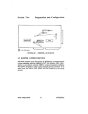
AHA-1540B/1542B 2-2 adaptec Section Two Preparation and Configuration Pin I MICROCODE IIIIIIIMINI J8 J9 Pin 1 BIOS = AHA-15408 Default FIGURE 2-1. JUMPER LOCATIONS 2.3 JUMPER CONFIGURATION All of the jumpers have been preset at the factory to ensure proper system operation with the majority of AT bus systems. This information is provided to help the OEM or system integrator configure the system properly if other option boards present conflicts or if more than one AHA-154X board will be installed in the same system.
AHA-1540B/1542B 2-2 adaptec Section Two Preparation and Configuration Pin I MICROCODE IIIIIIIMINI J8 J9 Pin 1 BIOS = AHA-15408 Default FIGURE 2-1. JUMPER LOCATIONS 2.3 JUMPER CONFIGURATION All of the jumpers have been preset at the factory to ensure proper system operation with the majority of AT bus systems. This information is provided to help the OEM or system integrator configure the system properly if other option boards present conflicts or if more than one AHA-154X board will be installed in the same system.

User Manual
Page 4
...-pin connector J2. If any attached AHA-15408/1542B 2-3 adaptec Default is shown below: - J9 must initiate the negotiation. Section Two Preparation and Configuration 2.3.1 Jumper Block J5 Jumper block J5 is jumper removed, synchronous negotiation initiation disabled. The AHA-1540B/1542B will still support synchronous SCSI transfers, but a different SCSI device must also be set Interrupt Channel...
...-pin connector J2. If any attached AHA-15408/1542B 2-3 adaptec Default is shown below: - J9 must initiate the negotiation. Section Two Preparation and Configuration 2.3.1 Jumper Block J5 Jumper block J5 is jumper removed, synchronous negotiation initiation disabled. The AHA-1540B/1542B will still support synchronous SCSI transfers, but a different SCSI device must also be set Interrupt Channel...
User Manual
Page 5
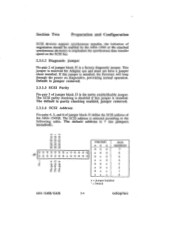
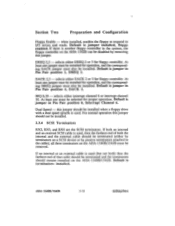
...) 0 0 0 0 (i) 0 0 0 0 0 0 0 x 0 0 0 0 0 0 0 0 0 0 0 0 x 0 0 0 0 0 PIN-PAIR 45 6 00 0 x0 0 0x 0 xx 0 00 x x0 x 0x x xx x SCSI ADDRESS 7* 6 5 4 3 2 1 0 x = Jumper Installed Default AHA-1540B/1542B 2-4 adaptec This jumper is selected according to implement the synchronous data transfer speed on diagnostics, preventing normal operation. The SCSI address is reserved for Adaptec use and must not have a jumper shunt installed. The default is the...
...) 0 0 0 0 (i) 0 0 0 0 0 0 0 x 0 0 0 0 0 0 0 0 0 0 0 0 x 0 0 0 0 0 PIN-PAIR 45 6 00 0 x0 0 0x 0 xx 0 00 x x0 x 0x x xx x SCSI ADDRESS 7* 6 5 4 3 2 1 0 x = Jumper Installed Default AHA-1540B/1542B 2-4 adaptec This jumper is selected according to implement the synchronous data transfer speed on diagnostics, preventing normal operation. The SCSI address is reserved for Adaptec use and must not have a jumper shunt installed. The default is the...
User Manual
Page 6
...reported to the AT during the Return Configuration command is DMA Request 5. Default is set by these jumpers according to the following diagrams: AHA-1540B/1542B 2-5 adaptec Pin pair 1 is the leftmost pair of pins. There are four DMA channels that may be used by using the jumper blocks and pin...and J9. Default is DMA Acknowledge 5. Jumper set is located near the bottom center of the host adapter. Jumper set up by the AHA-1540B/1542B according to the following table. The DMA channel is located near the bottom center of the host adapter. The jumper settings for use ...
...reported to the AT during the Return Configuration command is DMA Request 5. Default is set by these jumpers according to the following diagrams: AHA-1540B/1542B 2-5 adaptec Pin pair 1 is the leftmost pair of pins. There are four DMA channels that may be used by using the jumper blocks and pin...and J9. Default is DMA Acknowledge 5. Jumper set is located near the bottom center of the host adapter. Jumper set up by the AHA-1540B/1542B according to the following table. The DMA channel is located near the bottom center of the host adapter. The jumper settings for use ...

User Manual
Page 8
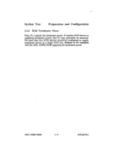
... following table. The default interrupt channel is interrupt channel 11. This jumper set by the AHA-1540B/1542B. Interrupt Channel Select bit 0 Interrupt Channel Select bit 1 Interrupt Channel Select bit 2 J5 INTERRUPT CHANNELS PIN-PAIR... 9 10 11* 12 14 15 0 0 0 0 0 0 0 0 0 x 0 0 0 J5 0 0 0 0 0 0 0 0 0 x 0 0 0 rn cs, a- al as a a0 tr. Pin pair 1 is located near the bottom center of jumper pin pairs J5. Section Two Preparation and Configuration 2.3.1.6 AT Interrupt Channel There are J5 and J9. b: x = Jumper Installed * = Default AHA-1540B/1542B 2-7 adaptec These ...
... following table. The default interrupt channel is interrupt channel 11. This jumper set by the AHA-1540B/1542B. Interrupt Channel Select bit 0 Interrupt Channel Select bit 1 Interrupt Channel Select bit 2 J5 INTERRUPT CHANNELS PIN-PAIR... 9 10 11* 12 14 15 0 0 0 0 0 0 0 0 0 x 0 0 0 J5 0 0 0 0 0 0 0 0 0 x 0 0 0 rn cs, a- al as a a0 tr. Pin pair 1 is located near the bottom center of jumper pin pairs J5. Section Two Preparation and Configuration 2.3.1.6 AT Interrupt Channel There are J5 and J9. b: x = Jumper Installed * = Default AHA-1540B/1542B 2-7 adaptec These ...
User Manual
Page 9
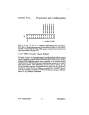
... selected after power on time) for any of jumper block J5 set any particular system by using the Host Adapter command Set Transfer Speed. AHA-15408/15428 2-8 adaptec This speed may also be installed in J5. 2.3.1.7 DMA Transfer Speed Default Pin-pairs 12 and 13 of four default DMA transfer speeds. (See... 'I' LO CD CD CD CD C C C C C C CCCCCC ( CO CO CO CD CO 8 8- 8cr Qcr •cr cc cr 000 Ox 0 00 0000x 000 x = Jumper Installed IRQ 9, 10, 11, 12, 14, 15 - connects the interrupt line to interrupt the Host.
... selected after power on time) for any of jumper block J5 set any particular system by using the Host Adapter command Set Transfer Speed. AHA-15408/15428 2-8 adaptec This speed may also be installed in J5. 2.3.1.7 DMA Transfer Speed Default Pin-pairs 12 and 13 of four default DMA transfer speeds. (See... 'I' LO CD CD CD CD C C C C C C CCCCCC ( CO CO CO CD CO 8 8- 8cr Qcr •cr cc cr 000 Ox 0 00 0000x 000 x = Jumper Installed IRQ 9, 10, 11, 12, 14, 15 - connects the interrupt line to interrupt the Host.
User Manual
Page 10
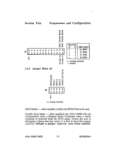
when installed, enables the BIOS Prom to CL 0_ co cCo L J6 x 0 0 0 0 x 0 0 0 0 C a- MIA-15408/1542B 2-9 adaptec Disable Auto Sense - Section Two Preparation and Configuration J5 0 0 0 0 0 0 0 0 0 0 0 0 0 0 x x 0 0 x x 0 0 0 0 0 0 CM C7 a- PIN-PAIR 12 13 0 0 x 0 0 x x x DMA Speed... = Default 2.3.2 Jumper Block J6 BIOS Enable Disable Auto Sense CV CI 2 co 2 Cl) 2 to be read. when installed, the AHA-1540B will not automatically issue a Request Sense Command when a check condition is best to leave this jumper removed. x = Jumper Installed BIOS...
when installed, enables the BIOS Prom to CL 0_ co cCo L J6 x 0 0 0 0 x 0 0 0 0 C a- MIA-15408/1542B 2-9 adaptec Disable Auto Sense - Section Two Preparation and Configuration J5 0 0 0 0 0 0 0 0 0 0 0 0 0 0 x x 0 0 x x 0 0 0 0 0 0 CM C7 a- PIN-PAIR 12 13 0 0 x 0 0 x x x DMA Speed... = Default 2.3.2 Jumper Block J6 BIOS Enable Disable Auto Sense CV CI 2 co 2 Cl) 2 to be read. when installed, the AHA-1540B will not automatically issue a Request Sense Command when a check condition is best to leave this jumper removed. x = Jumper Installed BIOS...
User Manual
Page 11
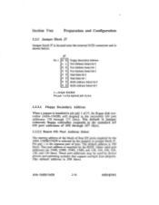
... pair 1 of J7, the floppy disk controller (AHA-1542B) will respond to the standard AT I /O ports required by the AHA-1540B/1542B is selected by device drivers and operating systems that support multiple host adapters. AHA-1540B/1542B 2-10 adaptec Other valid port addresses are 334H, 230H,... jumper removed; The default is 330 (hex). •S• Section Two Preparation and Configuration 2.3.3 Jumper Block J7 Jumper block J7 is located near the external SCSI connector and is shown below: Pin 1 J7 0 0 X X 0 0 0 0 0 0 0 0 0 0 0 0 Floppy Secondary Address Port Address Select bit ...
... pair 1 of J7, the floppy disk controller (AHA-1542B) will respond to the standard AT I /O ports required by the AHA-1540B/1542B is selected by device drivers and operating systems that support multiple host adapters. AHA-1540B/1542B 2-10 adaptec Other valid port addresses are 334H, 230H,... jumper removed; The default is 330 (hex). •S• Section Two Preparation and Configuration 2.3.3 Jumper Block J7 Jumper block J7 is located near the external SCSI connector and is shown below: Pin 1 J7 0 0 X X 0 0 0 0 0 0 0 0 0 0 0 0 Floppy Secondary Address Port Address Select bit ...
User Manual
Page 12
... be used Note that selection of 100, 200, or 300 nsec. x x x DELAY (ns) 0 (IOCHRDY not driven)* 100 200 300 x = Jumper Installed - = Jumper Not Installed = Default AHA-1540B/1542B 2-11 adaptec
... be used Note that selection of 100, 200, or 300 nsec. x x x DELAY (ns) 0 (IOCHRDY not driven)* 100 200 300 x = Jumper Installed - = Jumper Not Installed = Default AHA-1540B/1542B 2-11 adaptec
User Manual
Page 13
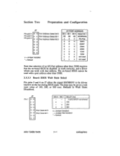
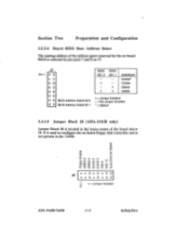
... 0 BIOS Address Select bit 1 BIOS BIOS SEL 0 SEL 1 x - x =Jumper Installed n_ AI-IA-15408/1542B 2-12 adaptec It is used to configure the on-board floppy disk controller and is selected by pin pairs 7 and 8 on -board BIOS is not present in the 1540B. Section Two Preparation... and Configuration 2.3.3.4 Board BIOS Base Address Select The starting address of the board above J9. No Jumper Installed * = Default 2.3.3.5 Jumper Block J8 (AHA-1542B...
... 0 BIOS Address Select bit 1 BIOS BIOS SEL 0 SEL 1 x - x =Jumper Installed n_ AI-IA-15408/1542B 2-12 adaptec It is used to configure the on-board floppy disk controller and is selected by pin pairs 7 and 8 on -board BIOS is not present in the 1540B. Section Two Preparation... and Configuration 2.3.3.4 Board BIOS Base Address Select The starting address of the board above J9. No Jumper Installed * = Default 2.3.3.5 Jumper Block J8 (AHA-1542B...
User Manual
Page 14
... Pin Pair position 4, DACK 2. Default is terminators installed. selects either DREQ 2 or 3 for floppy controller. all three terminators on the AHA-1542B can be disabled by removing this jumper. DREQ 2,3 - IRQ 6,10 - If both an internal and an external SCSI cable is used , then the farthest end of both ) then the farthest end of that... for operation, and the corresponding DACK jumper must also be installed when a floppy drive with a dual speed spindle is jumper in Pin Pair position 2, DREQ 2. AHA-1540B/1542B 2-13 adaptec
... Pin Pair position 4, DACK 2. Default is terminators installed. selects either DREQ 2 or 3 for floppy controller. all three terminators on the AHA-1542B can be disabled by removing this jumper. DREQ 2,3 - IRQ 6,10 - If both an internal and an external SCSI cable is used , then the farthest end of both ) then the farthest end of that... for operation, and the corresponding DACK jumper must also be installed when a floppy drive with a dual speed spindle is jumper in Pin Pair position 2, DREQ 2. AHA-1540B/1542B 2-13 adaptec
User Manual
Page 15
AFIA-1540B/1542B 2-14 adaptec Default is supplying terminator power, then Fl may optionally be configured to supply terminator power to a single SCSI bus. If another SCSI device is Fl installed with the AHA-1540B/1542B supplying the terminator power. No more than five SCSI devices should be removed. Section Two Preparation and Configuration 2.3.5 SCSI Terminator Power Fuse, Fl, controls the terminator power.
AFIA-1540B/1542B 2-14 adaptec Default is supplying terminator power, then Fl may optionally be configured to supply terminator power to a single SCSI bus. If another SCSI device is Fl installed with the AHA-1540B/1542B supplying the terminator power. No more than five SCSI devices should be removed. Section Two Preparation and Configuration 2.3.5 SCSI Terminator Power Fuse, Fl, controls the terminator power.
