Aspire X1200 / X3200 Service Guide
Page 3
Copyright Copyright © 2008 by any form or by Acer Incorporated. iii All rights reserved. No part of this publication may be reproduced, transmitted, transcribed, stored in a retrieval system, or translated into any language or computer language, in any means, electronic, mechanical, magnetic, optical, chemical, manual or otherwise, without the prior written permission of Acer Incorporated.
Copyright Copyright © 2008 by any form or by Acer Incorporated. iii All rights reserved. No part of this publication may be reproduced, transmitted, transcribed, stored in a retrieval system, or translated into any language or computer language, in any means, electronic, mechanical, magnetic, optical, chemical, manual or otherwise, without the prior written permission of Acer Incorporated.
Aspire X1200 / X3200 Service Guide
Page 6
... SERVICE PROVIDERS, your regional offices or the responsible personnel/channel to order FRU parts for repair and service of a machine (e.g. You MUST use the list provided by your regional Acer office to provide you with all technical information relating to -date information available on ...card, modem, or extra memory capability). add-on your regional office MAY have a DIFFERENT part number code to extend the functionality of customer...
... SERVICE PROVIDERS, your regional offices or the responsible personnel/channel to order FRU parts for repair and service of a machine (e.g. You MUST use the list provided by your regional Acer office to provide you with all technical information relating to -date information available on ...card, modem, or extra memory capability). add-on your regional office MAY have a DIFFERENT part number code to extend the functionality of customer...
Aspire X1200 / X3200 Service Guide
Page 15
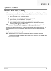
... values may not be retained when power is no need to be the same those found in a battery-backed nonvolatile memory called CMOS RAM. Ask a qualified technician for assistance. Before you repeatedly receive Run Setup messages, the battery may be simply referred to as "Setup"...system reboots immediately after you have saved all open files. Chapter 2 System Utilities Phoenix BIOS Setup Utility BIOS setup is not part of the system RAM which allows configuration data to run this utility under the following conditions. This memory area is a hardware configuration program built ...
... values may not be retained when power is no need to be the same those found in a battery-backed nonvolatile memory called CMOS RAM. Ask a qualified technician for assistance. Before you repeatedly receive Run Setup messages, the battery may be simply referred to as "Setup"...system reboots immediately after you have saved all open files. Chapter 2 System Utilities Phoenix BIOS Setup Utility BIOS setup is not part of the system RAM which allows configuration data to run this utility under the following conditions. This memory area is a hardware configuration program built ...
Aspire X1200 / X3200 Service Guide
Page 41
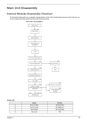
... READER BOARD BRACKET Dx2 Ax6, Cx1 MAINBOARD Screw #6-32 L5 BZN #6-32*3/16 NI M3xL5 BZN Hex screw Ax2 FRONT I/O BOARD Ax2 CARD READER BOARD Part No. 86.00J07.B60 86.5A5B6.012 86.1A324.5R0 N/A Chapter 3 33 Main Unit Disassembly External Modules Disassembly Flowchart The flowchart below gives you a graphic...
... READER BOARD BRACKET Dx2 Ax6, Cx1 MAINBOARD Screw #6-32 L5 BZN #6-32*3/16 NI M3xL5 BZN Hex screw Ax2 FRONT I/O BOARD Ax2 CARD READER BOARD Part No. 86.00J07.B60 86.5A5B6.012 86.1A324.5R0 N/A Chapter 3 33 Main Unit Disassembly External Modules Disassembly Flowchart The flowchart below gives you a graphic...
Aspire X1200 / X3200 Service Guide
Page 42
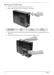
Slide the side panel toward the back of the side panel. Perform the pre-disassembly procedure described on the chassis. 4. Screw (Quantity) #6-32 L5 BZN (2) Color Black Torque 5.5 to 6.5 kgf-cm Part No. 86.00J07.B60 3. Lift the side panel away from the server and put it aside for reinstallation later. 34 Chapter 3 Removing the Side Panel 1. Remove the screw (A) located on the rear edge of the chassis until the tabs on the cover disengage with the slots on page 32. 2.
Slide the side panel toward the back of the side panel. Perform the pre-disassembly procedure described on the chassis. 4. Screw (Quantity) #6-32 L5 BZN (2) Color Black Torque 5.5 to 6.5 kgf-cm Part No. 86.00J07.B60 3. Lift the side panel away from the server and put it aside for reinstallation later. 34 Chapter 3 Removing the Side Panel 1. Remove the screw (A) located on the rear edge of the chassis until the tabs on the cover disengage with the slots on page 32. 2.
Aspire X1200 / X3200 Service Guide
Page 50
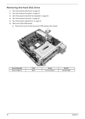
See "Removing the Heat Sink Fan Assembly" on page 35. 3. a. See "Removing the Font Bezel" on page 36. 4. Remove the HDD-ODD bracket. Remove the screw (A) that secures the HDD bracket to 6.5 kgf-cm Part No. 86.00J07.B60 42 Chapter 3 Screw (Quantity) #6-32 L5 BZN (1) Color Black Torque 5.5 to the chassis. See "Removing the Side Panel" on page 40. 6. Removing the Hard Disk Drive 1. See "Removing the Optical Drive" on page 34. 2. See "Removing the Processor" on page 38. 5.
See "Removing the Heat Sink Fan Assembly" on page 35. 3. a. See "Removing the Font Bezel" on page 36. 4. Remove the HDD-ODD bracket. Remove the screw (A) that secures the HDD bracket to 6.5 kgf-cm Part No. 86.00J07.B60 42 Chapter 3 Screw (Quantity) #6-32 L5 BZN (1) Color Black Torque 5.5 to the chassis. See "Removing the Side Panel" on page 40. 6. Removing the Hard Disk Drive 1. See "Removing the Optical Drive" on page 34. 2. See "Removing the Processor" on page 38. 5.
Aspire X1200 / X3200 Service Guide
Page 53
a. Remove the HDD module. Slide the HDD out of the bracket. Screw (Quantity) #6-32*3/16 NI (4) Color Silver b. Remove the four screws (B) that secures the HDD module to 6.5 kgf-cm Part No. 86.5A5B6.012 Chapter 3 45 Torque 5.5 to the HDD bracket. 11.
a. Remove the HDD module. Slide the HDD out of the bracket. Screw (Quantity) #6-32*3/16 NI (4) Color Silver b. Remove the four screws (B) that secures the HDD module to 6.5 kgf-cm Part No. 86.5A5B6.012 Chapter 3 45 Torque 5.5 to the HDD bracket. 11.
Aspire X1200 / X3200 Service Guide
Page 55
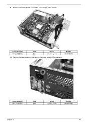
Screw (Quantity) #6-32 L5 BZN (1) Color Black Torque 5.5 to 6.5 kgf-cm Part No. 86.00J07.B60 Chapter 3 47 Screw (Quantity) #6-32 L5 BZN (3) Color Black Torque 5.5 to 6.5 kgf-cm Part No. 86.00J07.B60 10. 9. Remove the screw (A) that secure the power supply to the chassis. Remove the three screws (A) that secures the power supply to the rear panel.
Screw (Quantity) #6-32 L5 BZN (1) Color Black Torque 5.5 to 6.5 kgf-cm Part No. 86.00J07.B60 Chapter 3 47 Screw (Quantity) #6-32 L5 BZN (3) Color Black Torque 5.5 to 6.5 kgf-cm Part No. 86.00J07.B60 10. 9. Remove the screw (A) that secure the power supply to the chassis. Remove the three screws (A) that secures the power supply to the rear panel.
Aspire X1200 / X3200 Service Guide
Page 59
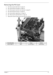
See "Removing the Optical Drive" on page 42. 7. See "Removing the Hard Disk Drive" on page 40. 6. Removing the PCI Card 1. Remove the screw (A) that secures the card to 6.5 kgf-cm Part No. 86.00J07.B60 Chapter 3 51 Screw (Quantity) #6-32 L5 BZN (1) Color Black Torque 5.5 to the chassis. See "Removing the Heat Sink Fan Assembly" on page 38. 5. See "Removing the Processor" on page 36. 4. See "Removing the Font Bezel" on page 34. 2. See "Removing the Side Panel" on page 35. 3.
See "Removing the Optical Drive" on page 42. 7. See "Removing the Hard Disk Drive" on page 40. 6. Removing the PCI Card 1. Remove the screw (A) that secures the card to 6.5 kgf-cm Part No. 86.00J07.B60 Chapter 3 51 Screw (Quantity) #6-32 L5 BZN (1) Color Black Torque 5.5 to the chassis. See "Removing the Heat Sink Fan Assembly" on page 38. 5. See "Removing the Processor" on page 36. 4. See "Removing the Font Bezel" on page 34. 2. See "Removing the Side Panel" on page 35. 3.

Aspire X1200 / X3200 Service Guide
Page 62
Remove the front I/O and card reader board bracket. Screw (Quantity) #6-32*3/16 NI (2) Color Silver Torque 5.5 to the chassis. Remove the two screws (B) that secures the bracket to 6.5 kgf-cm Part No. 86.5A5B6.012 54 Chapter 3 Disconnect the other end of the cables from the mainboard. 10. 9. a.
Remove the front I/O and card reader board bracket. Screw (Quantity) #6-32*3/16 NI (2) Color Silver Torque 5.5 to the chassis. Remove the two screws (B) that secures the bracket to 6.5 kgf-cm Part No. 86.5A5B6.012 54 Chapter 3 Disconnect the other end of the cables from the mainboard. 10. 9. a.
Aspire X1200 / X3200 Service Guide
Page 63
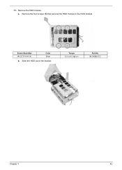
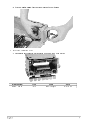
Push the bracket inward, then remove the bracket from the chassis. 11. Remove the two screws (A) that secure the card reader board to 6.5 kgf-cm Part No. 86.00J07.B60 Chapter 3 55 Screw (Quantity) #6-32 L5 BZN (2) Color Black Torque 5.5 to the bracket. Remove the card reader board. a. b.
Push the bracket inward, then remove the bracket from the chassis. 11. Remove the two screws (A) that secure the card reader board to 6.5 kgf-cm Part No. 86.00J07.B60 Chapter 3 55 Screw (Quantity) #6-32 L5 BZN (2) Color Black Torque 5.5 to the bracket. Remove the card reader board. a. b.
Aspire X1200 / X3200 Service Guide
Page 64
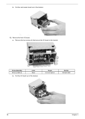
Pull the I /O board. Torque 5.5 to the bracket. Remove the two screws (A) that secure the I/O board to 6.5 kgf-cm Part No. 86.00J07.B60 56 Chapter 3 a. Screw (Quantity) #6-32 L5 BZN (2) Color Black b. Remove the front I /O board out of the bracket. 12. Pull the card reader board out of the bracket. b.
Pull the I /O board. Torque 5.5 to the bracket. Remove the two screws (A) that secure the I/O board to 6.5 kgf-cm Part No. 86.00J07.B60 56 Chapter 3 a. Screw (Quantity) #6-32 L5 BZN (2) Color Black b. Remove the front I /O board out of the bracket. 12. Pull the card reader board out of the bracket. b.
Aspire X1200 / X3200 Service Guide
Page 65
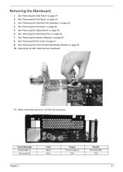
.... See "Removing the Front I/O and Card Reader Boards" on page 49. 8. Screw (Quantity) M3xL5 BZN (1) Hex screw (2) Chapter 3 Color Black Silver Torque 5.5 to 6.5 kgf-cm N/A Part No. 86.1A324.5R0 N/A 57 See "Removing the PCI Card" on page 51. 9.
.... See "Removing the Front I/O and Card Reader Boards" on page 49. 8. Screw (Quantity) M3xL5 BZN (1) Hex screw (2) Chapter 3 Color Black Silver Torque 5.5 to 6.5 kgf-cm N/A Part No. 86.1A324.5R0 N/A 57 See "Removing the PCI Card" on page 51. 9.
Aspire X1200 / X3200 Service Guide
Page 66
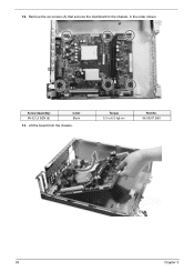
Torque 5.5 to the chassis, in the order shown. Remove the six screws (A) that secures the mainboard to 6.5 kgf-cm Part No. 86.00J07.B60 58 Chapter 3 Lift the board from the chassis. Screw (Quantity) #6-32 L5 BZN (6) Color Black 13. 12.
Torque 5.5 to the chassis, in the order shown. Remove the six screws (A) that secures the mainboard to 6.5 kgf-cm Part No. 86.00J07.B60 58 Chapter 3 Lift the board from the chassis. Screw (Quantity) #6-32 L5 BZN (6) Color Black 13. 12.
Aspire X1200 / X3200 Service Guide
Page 69
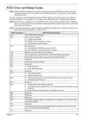
...the FRU replacement or actions in the sequence shown in FRU/Action column, if the FRU replacement does not solve the problem, put the original part back in the BIOS Setup Utility menus, reset the computer, enter Setup and install Setup defaults or correct the error. Others may indicate a... 04h 05h 06h 07h 08h 09h 0Ah 0Bh 0Ch 0Dh 0Eh 0Fh 10h 11h POST Routine Description Test CMOS R/W functionality Early chipset initialization T Disable shadow RAM T Disable L2 cache (socket 7 or below) T Program basic chipset registers Detect memory T Auto-detection of DRAM size, type, and ECC T Auto-detection...
...the FRU replacement or actions in the sequence shown in FRU/Action column, if the FRU replacement does not solve the problem, put the original part back in the BIOS Setup Utility menus, reset the computer, enter Setup and install Setup defaults or correct the error. Others may indicate a... 04h 05h 06h 07h 08h 09h 0Ah 0Bh 0Ch 0Dh 0Eh 0Fh 10h 11h POST Routine Description Test CMOS R/W functionality Early chipset initialization T Disable shadow RAM T Disable L2 cache (socket 7 or below) T Program basic chipset registers Detect memory T Auto-detection of DRAM size, type, and ECC T Auto-detection...
Aspire X1200 / X3200 Service Guide
Page 75
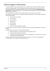
... a list of telephone, fax, and email contacts for all models T User's manuals T Training materials T BIOS updates T Software utilities T Spare parts lists T Technical Announcement Bulletins (TABs) For these to us. If you are also available in the Support & Downloads tab: T Detailed information on... Acer's International Traveler's Warranty (ITW) T Returned material authorization procedures T An overview of all the support services we have included an Acrobat ...
... a list of telephone, fax, and email contacts for all models T User's manuals T Training materials T BIOS updates T Software utilities T Spare parts lists T Technical Announcement Bulletins (TABs) For these to us. If you are also available in the Support & Downloads tab: T Detailed information on... Acer's International Traveler's Warranty (ITW) T Returned material authorization procedures T An overview of all the support services we have included an Acrobat ...
Aspire X1200 / X3200 Service Guide
Page 81
...Unit) list in the FRU list of the Aspire ASX1200/ ASX3200 desktop computer. For Acer authorized service providers, your Acer office may have a different part number code from those given in global configuration of this chapter whenever ordering the parts to order FRU parts for RMA (Return Merchandise Authorization). Chapter 6 ... return it. For whatever reasons a part number is changed, it properly, or follow the rules set by your regional web or channel. You MUST use the local FRU list provided by your regional Acer office on your regional Acer office to repair or for service. ...
...Unit) list in the FRU list of the Aspire ASX1200/ ASX3200 desktop computer. For Acer authorized service providers, your Acer office may have a different part number code from those given in global configuration of this chapter whenever ordering the parts to order FRU parts for RMA (Return Merchandise Authorization). Chapter 6 ... return it. For whatever reasons a part number is changed, it properly, or follow the rules set by your regional web or channel. You MUST use the local FRU list provided by your regional Acer office on your regional Acer office to repair or for service. ...
Aspire X1200 / X3200 Service Guide
Page 83
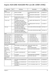
MB 1 SATA HDD CABLE (LONG) C.A. Aspire ASX1200/ ASX3200 FRU List (81.3V001.010G) Component QTY Part Name Description Acer Part Number Board Front I/O board 1 FRONT I/O BOARD DA078L/BOXER FRONT I /O holder 1 IO HOLDER SHIELDING REAR IO BOXER95 33.SAR01.002 HDD and ODD cover bracket 1 HDD&...
MB 1 SATA HDD CABLE (LONG) C.A. Aspire ASX1200/ ASX3200 FRU List (81.3V001.010G) Component QTY Part Name Description Acer Part Number Board Front I/O board 1 FRONT I/O BOARD DA078L/BOXER FRONT I /O holder 1 IO HOLDER SHIELDING REAR IO BOXER95 33.SAR01.002 HDD and ODD cover bracket 1 HDD&...
Aspire X1200 / X3200 Service Guide
Page 85
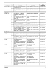
...50008.009 WD WD5000AAJS-22A8B0 LF F/ W:01.03A01 Chapter 6 77 Component Sempron, 45W Optical drive DVD-RW drive Hard disk drive 160 GB 250 GB 320 GB 500 GB QTY Part Name 1 CPU AMD 2.2G SDH1250IAA4DP SEMPRON LE-1250 1 CPU AMD 2.5G G2 SDH1300IAA4DP SEMPRON LE- 1300 Description IC CPU SEMPRON LE-1250... 2.2G IC CPU SEMPRON LE-1300 2.5G G2 Acer Part Number KC.SLE02.125 KC.SLE02.130 1 DVD-RW DRIVE BD 4X HLDS GGW...
...50008.009 WD WD5000AAJS-22A8B0 LF F/ W:01.03A01 Chapter 6 77 Component Sempron, 45W Optical drive DVD-RW drive Hard disk drive 160 GB 250 GB 320 GB 500 GB QTY Part Name 1 CPU AMD 2.2G SDH1250IAA4DP SEMPRON LE-1250 1 CPU AMD 2.5G G2 SDH1300IAA4DP SEMPRON LE- 1300 Description IC CPU SEMPRON LE-1250... 2.2G IC CPU SEMPRON LE-1300 2.5G G2 Acer Part Number KC.SLE02.125 KC.SLE02.130 1 DVD-RW DRIVE BD 4X HLDS GGW...
Aspire X1200 / X3200 Service Guide
Page 86
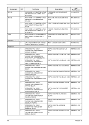
Component 640 GB 750 GB 1 TB Heat sink Keyboard QTY 1 1 1 1 1 Part Name HDD 640GB 3.5" 7200RPM SATA II WD WD6400AAKS-22A7B0 LF F/ W:01.03B01 HDD 750GB 3.5" 7200RPM SATA II SEAGATE ST3750840AS LF F/ W:3.AAD HDD 750GB 3.5" 7200RPM SATA ... 750G SATA 8MB 7200 NCQ HGST 750GB SATA 8MB 7200 NCQ HDD WD 750GB SATA 8MB 7200 NCQ HDD HGST 1TB SATA 8MB 7200 NCQ Acer Part Number KH.64008.001 KH.75001.003 KH.75007.001 KH.75008.001 KH.01K07.001 1 CPU COOLER WITH FAN LGA775 ASSY COOLER LGA775 ATX...
Component 640 GB 750 GB 1 TB Heat sink Keyboard QTY 1 1 1 1 1 Part Name HDD 640GB 3.5" 7200RPM SATA II WD WD6400AAKS-22A7B0 LF F/ W:01.03B01 HDD 750GB 3.5" 7200RPM SATA II SEAGATE ST3750840AS LF F/ W:3.AAD HDD 750GB 3.5" 7200RPM SATA ... 750G SATA 8MB 7200 NCQ HGST 750GB SATA 8MB 7200 NCQ HDD WD 750GB SATA 8MB 7200 NCQ HDD HGST 1TB SATA 8MB 7200 NCQ Acer Part Number KH.64008.001 KH.75001.003 KH.75007.001 KH.75008.001 KH.01K07.001 1 CPU COOLER WITH FAN LGA775 ASSY COOLER LGA775 ATX...


