Service Guide
Page 7
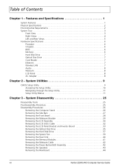
... 40 Removing the Memory Modules 41 Removing the Webcam Cable 42 Removing the Power Button/LED Assembly 42 Removing the Speakers 43 Removing the Mainboard 44 vii Veriton Z290G AIO Computer Service Guide System Utilities 9 CMOS Setup Utility 9 Accessing the Setup Utility 10 Navigating through the Setup Utility 11 Setup Utility Menus 11...
... 40 Removing the Memory Modules 41 Removing the Webcam Cable 42 Removing the Power Button/LED Assembly 42 Removing the Speakers 43 Removing the Mainboard 44 vii Veriton Z290G AIO Computer Service Guide System Utilities 9 CMOS Setup Utility 9 Accessing the Setup Utility 10 Navigating through the Setup Utility 11 Setup Utility Menus 11...

Service Guide
Page 8
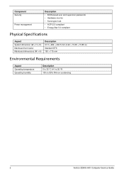
Table of Contents Chapter 4 - Troubleshooting 47 Hardware Diagnostic Procedure 47 System Check Procedures 47 Checkpoints 48 POST Error Indicators 52 BIOS Recovery 61 Clearing CMOS 62 Chapter 5 - Field Replaceable Unit (FRU) List 67 Exploded Diagram 68 FRU List 69 Appendix A - Model Definitions and Configurations 79 Appendix B - Test Compatible Components 81 Approved Vendor List (AVL 83 Appendix C - Online Support Information 93 Index 95 Veriton Z290G AIO Computer Service Guide viii System Architecture 63 Block Diagram 63 Mainboard Layout 64 Chapter 6 -
Table of Contents Chapter 4 - Troubleshooting 47 Hardware Diagnostic Procedure 47 System Check Procedures 47 Checkpoints 48 POST Error Indicators 52 BIOS Recovery 61 Clearing CMOS 62 Chapter 5 - Field Replaceable Unit (FRU) List 67 Exploded Diagram 68 FRU List 69 Appendix A - Model Definitions and Configurations 79 Appendix B - Test Compatible Components 81 Approved Vendor List (AVL 83 Appendix C - Online Support Information 93 Index 95 Veriton Z290G AIO Computer Service Guide viii System Architecture 63 Block Diagram 63 Mainboard Layout 64 Chapter 6 -
Service Guide
Page 10
... (W × H × D) Mainboard form factor Mainboard dimensions (W × H) Description 61.5 × 484 × 402.5 mm (2.42 × 19.05 × 15.85 in) Standard DTX 190 × 175 mm Environmental Requirements Aspect Operating temperature Operating humidity Description 5 to 35 °C (41 to 95 °F) 15% to 80% RH non-condensing 2 Veriton Z290G AIO Computer...
... (W × H × D) Mainboard form factor Mainboard dimensions (W × H) Description 61.5 × 484 × 402.5 mm (2.42 × 19.05 × 15.85 in) Standard DTX 190 × 175 mm Environmental Requirements Aspect Operating temperature Operating humidity Description 5 to 35 °C (41 to 95 °F) 15% to 80% RH non-condensing 2 Veriton Z290G AIO Computer...
Service Guide
Page 17
You will be retained when power is detected by the system and you repeatedly receive "Run Setup" messages, the RTC battery located on the mainboard (BT1) may be defective. POST uses these values to resolve IRQ conflicts • When a configuration error is turned off. You must run this Service Guide. ..., there is not part of reading, CMOS Setup Utility will need to as "Setup" or "Setup Utility" in a battery-backed nonvolatile memory called CMOS RAM. Veriton Z290G Service Guide 9 System Utilities Chapter 2 CMOS Setup Utility CMOS Setup Utility is booted.
You will be retained when power is detected by the system and you repeatedly receive "Run Setup" messages, the RTC battery located on the mainboard (BT1) may be defective. POST uses these values to resolve IRQ conflicts • When a configuration error is turned off. You must run this Service Guide. ..., there is not part of reading, CMOS Setup Utility will need to as "Setup" or "Setup Utility" in a battery-backed nonvolatile memory called CMOS RAM. Veriton Z290G Service Guide 9 System Utilities Chapter 2 CMOS Setup Utility CMOS Setup Utility is booted.

Service Guide
Page 27
Frequency/Voltage Control Field Spread Spectrum Processor Multiplier Description Value When the mainboard's clock generator pulses, the extreme values of the pulses creates EMI (electromagnetic interference). A slight jitter can introduce a temporary boost in the area. Set this field ... is only visible if an engineering processor installed. This reduces interference problems with other electronics in clock speed causing the overclocked processor to lock up. Veriton Z290G Service Guide 19 Enabled Disabled This field is disabled. Note: Remember to reduce this EMI level.
Frequency/Voltage Control Field Spread Spectrum Processor Multiplier Description Value When the mainboard's clock generator pulses, the extreme values of the pulses creates EMI (electromagnetic interference). A slight jitter can introduce a temporary boost in the area. Set this field ... is only visible if an engineering processor installed. This reduces interference problems with other electronics in clock speed causing the overclocked processor to lock up. Veriton Z290G Service Guide 19 Enabled Disabled This field is disabled. Note: Remember to reduce this EMI level.

Service Guide
Page 39
Veriton Z290G AIO Computer Service Guide 31 Disconnect the touchscreen film cable from both the mainboard and the touchscreen control board. Disconnect the touchscreen function cable from the touchscreen control board. 6. 4. Disconnect the LCD and inverter cables from the mainboard. 5.
Veriton Z290G AIO Computer Service Guide 31 Disconnect the touchscreen film cable from both the mainboard and the touchscreen control board. Disconnect the touchscreen function cable from the touchscreen control board. 6. 4. Disconnect the LCD and inverter cables from the mainboard. 5.
Service Guide
Page 43
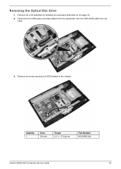
Remove the screw securing the ODD bracket to the chassis. Quantity 1 Color Chrome Torque 4.0 +/- 0.3 kgf.cm Part Number 86.00K96.644 Veriton Z290G AIO Computer Service Guide 35 Disconnect the ODD power and data cables from the mainboard, then the ODD SATA cable from the ODD. 3. Removing the Optical Disc Drive 1. Remove the LCD assembly by following the procedure described on the page 30. 2.
Remove the screw securing the ODD bracket to the chassis. Quantity 1 Color Chrome Torque 4.0 +/- 0.3 kgf.cm Part Number 86.00K96.644 Veriton Z290G AIO Computer Service Guide 35 Disconnect the ODD power and data cables from the mainboard, then the ODD SATA cable from the ODD. 3. Removing the Optical Disc Drive 1. Remove the LCD assembly by following the procedure described on the page 30. 2.

Service Guide
Page 47
Quantity 2 Color Chrome Torque 2.0 +/- 0.2 kgf.cm Part Number 86.7A122.4R0 Veriton Z290G AIO Computer Service Guide 39 Remove the LCD assembly by following the procedure described on the page 30. 2. Removing the System Fan 1. Disconnect the system fan cable from the mainboard. 3. Remove the screw securing the system fan.
Quantity 2 Color Chrome Torque 2.0 +/- 0.2 kgf.cm Part Number 86.7A122.4R0 Veriton Z290G AIO Computer Service Guide 39 Remove the LCD assembly by following the procedure described on the page 30. 2. Removing the System Fan 1. Disconnect the system fan cable from the mainboard. 3. Remove the screw securing the system fan.
Service Guide
Page 50
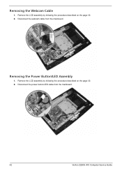
Removing the Webcam Cable 1. Remove the LCD assembly by following the procedure described on the page 30. 2. Removing the Power Button/LED Assembly 1. Remove the LCD assembly by following the procedure described on the page 30. 2. Disconnect the power button/LED cable from the mainboard. Disconnect the webcam cable from the mainboard. 42 Veriton Z290G AIO Computer Service Guide
Removing the Webcam Cable 1. Remove the LCD assembly by following the procedure described on the page 30. 2. Removing the Power Button/LED Assembly 1. Remove the LCD assembly by following the procedure described on the page 30. 2. Disconnect the power button/LED cable from the mainboard. Disconnect the webcam cable from the mainboard. 42 Veriton Z290G AIO Computer Service Guide

Service Guide
Page 51
Remove the power button/LED assembly from the mainboard. Veriton Z290G AIO Computer Service Guide 43 Remove the LCD assembly by following the procedure described on the page 30. 2. Disconnect the speaker cable from the front bezel. Removing the Speakers 1. 3.
Remove the power button/LED assembly from the mainboard. Veriton Z290G AIO Computer Service Guide 43 Remove the LCD assembly by following the procedure described on the page 30. 2. Disconnect the speaker cable from the front bezel. Removing the Speakers 1. 3.
Service Guide
Page 52
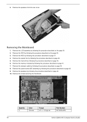
...Color Chrome Torque 4.5 +/- 0.3 kgf.cm Part Number 86.7A554.6R0 44 Veriton Z290G AIO Computer Service Guide 3. Remove the system fan by following the procedure described on page 42. 9. Remove the screws securing the mainboard. Remove the power button/LED assembly by following the procedure described on page... 39. 5. Remove the ODD by following the procedure described on page 43. 10. Removing the Mainboard 1. Remove the speakers by following the procedure described on the page 35. 3. Remove the speakers from the rear cover. Remove...
...Color Chrome Torque 4.5 +/- 0.3 kgf.cm Part Number 86.7A554.6R0 44 Veriton Z290G AIO Computer Service Guide 3. Remove the system fan by following the procedure described on page 42. 9. Remove the screws securing the mainboard. Remove the power button/LED assembly by following the procedure described on page... 39. 5. Remove the ODD by following the procedure described on page 43. 10. Removing the Mainboard 1. Remove the speakers by following the procedure described on the page 35. 3. Remove the speakers from the rear cover. Remove...

Service Guide
Page 53
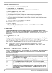
11. Detach the RTC battery and follow local regulations for disposing this type of circuit board. • The RTC battery has been highlighted with a yellow rectangle as shown in the above image. Remove the mainboard. • A circuit board that is >10 cm2 has been highlighted with a yellow circle in the above image. Veriton Z290G AIO Computer Service Guide 45 Follow local regulations for disposing it.
11. Detach the RTC battery and follow local regulations for disposing this type of circuit board. • The RTC battery has been highlighted with a yellow rectangle as shown in the above image. Remove the mainboard. • A circuit board that is >10 cm2 has been highlighted with a yellow circle in the above image. Veriton Z290G AIO Computer Service Guide 45 Follow local regulations for disposing it.
Service Guide
Page 56
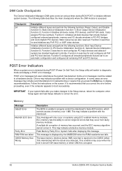
... drives. 8. Disable CACHE before system memory is enabled. 48 Veriton Z290G AIO Computer Service Guide If memory sizing module not executed, start memory refresh and do memory sizing in PCI devices. These are Acer-qualified and supported. 10. This display method is limited, since... it only displays checkpoints that flat mode is available. Checkpoint Before D1 D1 D0 D2 D3 Description Early chipset initialization is either a byte or word value output to their appropriate mainboard connectors...
... drives. 8. Disable CACHE before system memory is enabled. 48 Veriton Z290G AIO Computer Service Guide If memory sizing module not executed, start memory refresh and do memory sizing in PCI devices. These are Acer-qualified and supported. 10. This display method is limited, since... it only displays checkpoints that flat mode is available. Checkpoint Before D1 D1 D0 D2 D3 Description Early chipset initialization is either a byte or word value output to their appropriate mainboard connectors...
Service Guide
Page 60
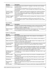
...problem with the mainboard. Function 2 searches for and configures PCI input devices and detects if system has standard keyboard controller. Initialize different buses and perform the following table describes the main checkpoints where the DIM module is corrupted. 52 Veriton Z290G AIO Computer Service...4); Fatal Memory Parity Error. Function 4 searches for troubleshooting or require that is detected during BIOS POST to properly control the mainboard's Gate A20 function, which controls access of memory has occurred, and the ECC memory algorithm cannot correct it. System halts after...
...problem with the mainboard. Function 2 searches for and configures PCI input devices and detects if system has standard keyboard controller. Initialize different buses and perform the following table describes the main checkpoints where the DIM module is corrupted. 52 Veriton Z290G AIO Computer Service...4); Fatal Memory Parity Error. Function 4 searches for troubleshooting or require that is detected during BIOS POST to properly control the mainboard's Gate A20 function, which controls access of memory has occurred, and the ECC memory algorithm cannot correct it. System halts after...
Service Guide
Page 63
.... BIOS could not find or load the CPU Microcode Update to the NVRAM block. There was not used for system configuration in a mainboard with system hardware. Status BAD, Backup and Replace S.M.A.R.T. BIOS could not write to the CPU. This causes POST to a drive's boot...) data was not used to a data error. Description The BIOS has detected software attempting to write to clear the NVRAM data. Veriton Z290G AIO Computer Service Guide 55 Virus-related Message BootSector Write!! The NVRAM data used for system configuration in POST due to store Plug...
.... BIOS could not find or load the CPU Microcode Update to the NVRAM block. There was not used for system configuration in a mainboard with system hardware. Status BAD, Backup and Replace S.M.A.R.T. BIOS could not write to the CPU. This causes POST to a drive's boot...) data was not used to a data error. Description The BIOS has detected software attempting to write to clear the NVRAM data. Veriton Z290G AIO Computer Service Guide 55 Virus-related Message BootSector Write!! The NVRAM data used for system configuration in POST due to store Plug...
Service Guide
Page 65
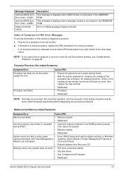
... the system. • Memory module • Mainboard System works but the fan still does not work . • IDE drive connection/cables • IDE disk drives • See "Undetermined Problems". • Mainboard Veriton Z290G AIO Computer Service Guide 57 system does not work... , then replace the heat sink fan. • Mainboard • Processor • Mainboard NOTE Normally, the processor fan should be operative, and the processor ...
... the system. • Memory module • Mainboard System works but the fan still does not work . • IDE drive connection/cables • IDE disk drives • See "Undetermined Problems". • Mainboard Veriton Z290G AIO Computer Service Guide 57 system does not work... , then replace the heat sink fan. • Mainboard • Processor • Mainboard NOTE Normally, the processor fan should be operative, and the processor ...
Service Guide
Page 66
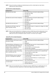
... Action/FRU • Enter CMOS Setup and load the default settings. • Hard disk drive cable • Hard disk drive • Mainboard • Enter CMOS Setup and load the default settings. • Hard disk drive cable • Hard disk drive •... • Mainboard CD/DVD-ROM drive LED flashes for more than 30 seconds before diagnosing any system problems. Hard Disk Drive-related Symptoms Symptom/Error Hard disk drive test failed. but system operates normally. no messages are clean before diagnosing any optical drive problems. 58 Veriton Z290G AIO Computer Service...
... Action/FRU • Enter CMOS Setup and load the default settings. • Hard disk drive cable • Hard disk drive • Mainboard • Enter CMOS Setup and load the default settings. • Hard disk drive cable • Hard disk drive •... • Mainboard CD/DVD-ROM drive LED flashes for more than 30 seconds before diagnosing any system problems. Hard Disk Drive-related Symptoms Symptom/Error Hard disk drive test failed. but system operates normally. no messages are clean before diagnosing any optical drive problems. 58 Veriton Z290G AIO Computer Service...
Service Guide
Page 67
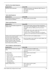
...Win 98, ensure the telephone application is configured correctly for your modem and set correctly. • RTC battery • Mainboard Audio-related Symptoms Symptom/Error Audio software program invoked but system sound feature works normally.) • Ensure the modem voice-...8226; Ensure the modem card is readable). • Mainboard • Monitor signal connection/cable • Monitor • Video adapter card • Mainboard • Monitor signal connection/cable • Video adapter card • Mainboard Veriton Z290G AIO Computer Service Guide 59 Real-Time Clock-related ...
...Win 98, ensure the telephone application is configured correctly for your modem and set correctly. • RTC battery • Mainboard Audio-related Symptoms Symptom/Error Audio software program invoked but system sound feature works normally.) • Ensure the modem voice-...8226; Ensure the modem card is readable). • Mainboard • Monitor signal connection/cable • Monitor • Video adapter card • Mainboard • Monitor signal connection/cable • Video adapter card • Mainboard Veriton Z290G AIO Computer Service Guide 59 Real-Time Clock-related ...
Service Guide
Page 68
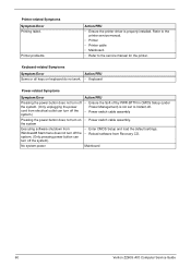
... not set to the service manual for the printer. Refer to the printer service manual. • Printer • Printer cable • Mainboard. • Refer to Instant-off. Windows98 Start menu does not turn off the system). Printer-related Symptoms Symptom/Error Printing failed. the ...-BTTN in CMOS Setup (under the system. (Only unplugging the power Power Management) is properly installed. No system power Mainboard 60 Veriton Z290G AIO Computer Service Guide Keyboard-related Symptoms Symptom/Error Action/FRU Some or all keys on • Power switch cable assembly.
... not set to the service manual for the printer. Refer to the printer service manual. • Printer • Printer cable • Mainboard. • Refer to Instant-off. Windows98 Start menu does not turn off the system). Printer-related Symptoms Symptom/Error Printing failed. the ...-BTTN in CMOS Setup (under the system. (Only unplugging the power Power Management) is properly installed. No system power Mainboard 60 Veriton Z290G AIO Computer Service Guide Keyboard-related Symptoms Symptom/Error Action/FRU Some or all keys on • Power switch cable assembly.
Service Guide
Page 70
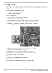
... Setup configuration values (CMOS) if the configuration has been corrupted, or if incorrect settings made and close the Setup Utility. 62 Veriton Z290G AIO Computer Service Guide Use the CMOS1 jumper to be unreadable. Return the jumper block to the computer and all peripherals. 2. ...on the computer. 13. Press the power button to the system. 12. Remove the LCD assembly by following the procedure described on the mainboard. 7. Reinstall all connected peripheral devices from the computer. 3. Turn off the power to its default 1-2 position. 9. This procedure will clear...
... Setup configuration values (CMOS) if the configuration has been corrupted, or if incorrect settings made and close the Setup Utility. 62 Veriton Z290G AIO Computer Service Guide Use the CMOS1 jumper to be unreadable. Return the jumper block to the computer and all peripherals. 2. ...on the computer. 13. Press the power button to the system. 12. Remove the LCD assembly by following the procedure described on the mainboard. 7. Reinstall all connected peripheral devices from the computer. 3. Turn off the power to its default 1-2 position. 9. This procedure will clear...

