
Veriton 5100/7100 Service Guide
Page 3
III NOTE WARNING CAUTION IMPORTANT Gives bits and pieces of procedures. Gives precautionary measures to avoid possible hardware or software problems. Reminds you to the current topic. Conventions The following conventions are used in this manual: Screen messages Denotes actual messages that might result from doing or not doing specific actions. Alerts you to do specific actions relevant to the accomplishment of additional information related to any damage that appear on screen.
III NOTE WARNING CAUTION IMPORTANT Gives bits and pieces of procedures. Gives precautionary measures to avoid possible hardware or software problems. Reminds you to the current topic. Conventions The following conventions are used in this manual: Screen messages Denotes actual messages that might result from doing or not doing specific actions. Alerts you to do specific actions relevant to the accomplishment of additional information related to any damage that appear on screen.
Veriton 5100/7100 Service Guide
Page 5
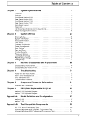
... Machine Disassembly and Replacement 55 Disassembling Veriton 5100 56 Disasembling the Veriton 7100 63 Chapter 4 Troubleshooting 71 Power-On Self-Test (POST 72 POST Error Messages List 73 Error Symptoms List 75 Undetermined Problems 79 Chapter 5 Jumper and Connector ...Information 81 Jumpers and Connectors 81 Chapter 6 FRU (Field Replaceable Unit) List 85 Veriton 5100 Exploded Diagram 86 Veriton 7100 Exploded Diagram 87 Appendix A Model Definition and Configuration 97 Veriton 5100 97 Veriton 7100 98...
... Machine Disassembly and Replacement 55 Disassembling Veriton 5100 56 Disasembling the Veriton 7100 63 Chapter 4 Troubleshooting 71 Power-On Self-Test (POST 72 POST Error Messages List 73 Error Symptoms List 75 Undetermined Problems 79 Chapter 5 Jumper and Connector ...Information 81 Jumpers and Connectors 81 Chapter 6 FRU (Field Replaceable Unit) List 85 Veriton 5100 Exploded Diagram 86 Veriton 7100 Exploded Diagram 87 Appendix A Model Definition and Configuration 97 Veriton 5100 97 Veriton 7100 98...
Veriton 5100/7100 Service Guide
Page 77
Index of Error Codes and Error Beeps ! Index of Error Messages ! Power-On Self-Test (POST) ! Undetermined Problems Chapter 4 Chapter 4 71 Troubleshooting This chapter provides troubleshooting information for the Veriton 5100/7100: ! Index of Error Symptoms !
Index of Error Codes and Error Beeps ! Index of Error Messages ! Power-On Self-Test (POST) ! Undetermined Problems Chapter 4 Chapter 4 71 Troubleshooting This chapter provides troubleshooting information for the Veriton 5100/7100: ! Index of Error Symptoms !
Veriton 5100/7100 Service Guide
Page 79
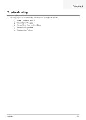
... board 1. Remove all adapter cards that are NOT factory- Enter BIOS Setup and load the default settings. 2. Chapter 4 73 NOTE: To diagnose a problem, first find the BIOS error messages in the DIMM sockets properly, then reboot the system. 2. Ensure BIOS setting for a description of your error symptoms in... "Error Symptoms List" on page 79. Ensure the system configuration set in BIOS Setup is set to correct the problem by the change. Insert the memory modules in the left column. Enter BIOS Setup to a check procedure, replace the FRU indicated in ...
... board 1. Remove all adapter cards that are NOT factory- Enter BIOS Setup and load the default settings. 2. Chapter 4 73 NOTE: To diagnose a problem, first find the BIOS error messages in the DIMM sockets properly, then reboot the system. 2. Ensure BIOS setting for a description of your error symptoms in... "Error Symptoms List" on page 79. Ensure the system configuration set in BIOS Setup is set to correct the problem by the change. Insert the memory modules in the left column. Enter BIOS Setup to a check procedure, replace the FRU indicated in ...

Veriton 5100/7100 Service Guide
Page 81
... be +12Vdc. 3. System board Incorrect memory size shown or repeated during POST. 1. Memory module. 3. System hangs before diagnosing any system problems. Memory test failed. 1. Blinking cursor only; Diskette/IDE disk drives 3. Diskette drive connection/cable 4. System board Chapter 4 75 Ensure the... 2. system does not work . 1. System board Diskette Drive NOTE: Ensure the diskette drive is clean before diagnosing any processor problems. Processor fan does not run but fails to match its read/write head is configured correctly in the Disk Drives of BIOS ...
... be +12Vdc. 3. System board Incorrect memory size shown or repeated during POST. 1. Memory module. 3. System hangs before diagnosing any system problems. Memory test failed. 1. Blinking cursor only; Diskette/IDE disk drives 3. Diskette drive connection/cable 4. System board Chapter 4 75 Ensure the... 2. system does not work . 1. System board Diskette Drive NOTE: Ensure the diskette drive is clean before diagnosing any processor problems. Processor fan does not run but fails to match its read/write head is configured correctly in the Disk Drives of BIOS ...

Veriton 5100/7100 Service Guide
Page 82
Ensure the diskette drive is not set correctly before diagnosing any CD/DVD-ROM drive problems. CD/DVD-ROM drive LED doesn't come on it . System board Diskette drive LED fails to light, and the drive is pressed and held. 1. Diskette 2. ... on it . System board. CD/DVD-ROM drive CD/DVD-ROM drive LED flashes for more than 30 seconds before diagnosing any hard disk drive problems. Hard disk drive test failed. 1. Hard disk drive cannot format completely. 1. CD/DVD-ROM is installed properly. 3. Error Symptom Action/FRU Diskette drive read and...
Ensure the diskette drive is not set correctly before diagnosing any CD/DVD-ROM drive problems. CD/DVD-ROM drive LED doesn't come on it . System board Diskette drive LED fails to light, and the drive is pressed and held. 1. Diskette 2. ... on it . System board. CD/DVD-ROM drive CD/DVD-ROM drive LED flashes for more than 30 seconds before diagnosing any hard disk drive problems. Hard disk drive test failed. 1. Hard disk drive cannot format completely. 1. CD/DVD-ROM is installed properly. 3. Error Symptom Action/FRU Diskette drive read and...

Veriton 5100/7100 Service Guide
Page 83
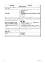
... Missing, broken, or incorrect characters Blank monitor(dark) Blank monitor(bright) Distorted image Unreadable monitor Other monitor problems Display changing colors. Display problem not listed above (including blank or illegible monitor). Ensure the headphone jack of BIOS Setup is set correctly....System board 1. Load default settings (if screen is used , ensure the modem ring-in cable from modem adapter card to Enabled. 2. Display problem: - Action/FRU 1. In Win 98, ensure the telephone application is installed properly. 1. Remove all non-factory-installed cards. 2. Video adapter...
... Missing, broken, or incorrect characters Blank monitor(dark) Blank monitor(bright) Distorted image Unreadable monitor Other monitor problems Display changing colors. Display problem not listed above (including blank or illegible monitor). Ensure the headphone jack of BIOS Setup is set correctly....System board 1. Load default settings (if screen is used , ensure the modem ring-in cable from modem adapter card to Enabled. 2. Display problem: - Action/FRU 1. In Win 98, ensure the telephone application is installed properly. 1. Remove all non-factory-installed cards. 2. Video adapter...
Veriton 5100/7100 Service Guide
Page 84
... Windows98 Start menu does not turn off the system. (Only pressing power switch can turn off the system). 1. System Board Other Problems Any other problems. 1. Error Symptom Action/FRU Parallel/Serial Ports Execute "Load BIOS Default Settings" in BIOS Setup. 2. System board. in BIOS ...the power override switch (situated at the back of Power Management is not set to confirm ports presence before diagnosing any parallel/serial ports problems. Serial or parallel port loop-back test failed. 1. Load default settings. 2. Refer to the service manual for the power cable)...
... Windows98 Start menu does not turn off the system. (Only pressing power switch can turn off the system). 1. System Board Other Problems Any other problems. 1. Error Symptom Action/FRU Parallel/Serial Ports Execute "Load BIOS Default Settings" in BIOS Setup. 2. System board. in BIOS ...the power override switch (situated at the back of Power Management is not set to confirm ports presence before diagnosing any parallel/serial ports problems. Serial or parallel port loop-back test failed. 1. Load default settings. 2. Refer to the service manual for the power cable)...

Veriton 5100/7100 Service Guide
Page 85
... correct, remove or disconnect the following checks, one by one at a time: 10. External devices ! System board 11. Chapter 4 79 If you have isolated the problem FRU. 4. Check all cables and connectors for proper installation. 9. Check the power supply voltages. DIMM ! Perform the following , one , until you still cannot solve the...
... correct, remove or disconnect the following checks, one by one at a time: 10. External devices ! System board 11. Chapter 4 79 If you have isolated the problem FRU. 4. Check all cables and connectors for proper installation. 9. Check the power supply voltages. DIMM ! Perform the following , one , until you still cannot solve the...

Veriton 5100/7100 Service Guide
Page 120
... 49 Power Management 39 Product Information 32 System Security 44 Time 43 T Temperature 23 Test Compatible Components 99 Time 43 Troubleshooting 71 U UART 20 Undetermined Problems 79 Universal HCI 20 USB Port 20 USB ports 7, 10 V VGA Palette Snoop 49 Vibration 23 video controller 18 Video controller 18 Voltage 24 Voltage...
... 49 Power Management 39 Product Information 32 System Security 44 Time 43 T Temperature 23 Test Compatible Components 99 Time 43 Troubleshooting 71 U UART 20 Undetermined Problems 79 Universal HCI 20 USB Port 20 USB ports 7, 10 V VGA Palette Snoop 49 Vibration 23 video controller 18 Video controller 18 Voltage 24 Voltage...


