

PD726W Service Guide
Page 13
VGA ADC DVI/HDMI Video Video Decoder USB RS232 Keypad IR Remote WIRELESS I/F DC-DC 13V 5V 3.3V POWER SUPPLIES CLOCK FLASH BOOT/ GENERATION EEPROM RLDRAM 30 PORT3 PORT2 PORT1 8 DDP3020 ASIC LVDS DMD I/F DAD1000 reset ASIC 1.5V 2.5V 1.8V uP8051 3.3V 3.3V ANALOG 5V THERMAL SENSER FANs CW DRIVER CW index CW Motor Ballast ballast control
VGA ADC DVI/HDMI Video Video Decoder USB RS232 Keypad IR Remote WIRELESS I/F DC-DC 13V 5V 3.3V POWER SUPPLIES CLOCK FLASH BOOT/ GENERATION EEPROM RLDRAM 30 PORT3 PORT2 PORT1 8 DDP3020 ASIC LVDS DMD I/F DAD1000 reset ASIC 1.5V 2.5V 1.8V uP8051 3.3V 3.3V ANALOG 5V THERMAL SENSER FANs CW DRIVER CW index CW Motor Ballast ballast control
PD726W Service Guide
Page 17
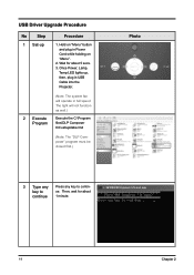
USB Driver Upgrade Procedure No Step 1 Set-up , then, plug in USB Cable into the Projector. (Note: The system fan will not function as well.) Execute the C:\...
USB Driver Upgrade Procedure No Step 1 Set-up , then, plug in USB Cable into the Projector. (Note: The system fan will not function as well.) Execute the C:\...

PD726W Service Guide
Page 18
DLPTM Processor", then, Driver" are properly installed. Photo 5 Device 1. Select "Properties" on the desktop. 2. Choose "Hardware" and then click "Device Manager". 6 Ensure Click "Jungo" to launch the "System Properties" ... In 1 minute, click "OK". Chapter2 Device Manager 12 Right click "My Manager computer" on the popup menu to ensure "DDP3020" "Texas Instruments & "Win- The USB driver is installed "DDP3020" or not. If not, repeart Step 1~5. Also, "Windriver" are click "General" and properly check if the Location is updated successfully.
DLPTM Processor", then, Driver" are properly installed. Photo 5 Device 1. Select "Properties" on the desktop. 2. Choose "Hardware" and then click "Device Manager". 6 Ensure Click "Jungo" to launch the "System Properties" ... In 1 minute, click "OK". Chapter2 Device Manager 12 Right click "My Manager computer" on the popup menu to ensure "DDP3020" "Texas Instruments & "Win- The USB driver is installed "DDP3020" or not. If not, repeart Step 1~5. Also, "Windriver" are click "General" and properly check if the Location is updated successfully.
PD726W Service Guide
Page 20
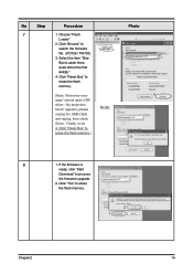
Click "Reset Bus" to erase the flash memory. (Note: If the error mes- 4 sage "cannot open USB driver - Click "Reset Bus" to erase the flash memory.) 8 1. If the firmware is ready, click "Start Download" to erase the flash memory. 2 1 Chapter2 ... search the firmware 1 file. (PD726 / PH730) 2 3. Finally, re-do 4. No projectors found" appears, please Note: unplug the USB Cable and replug, then check Driver. Select the item "Skip 3 Boot Loader Area (load all but the first 64KB)." 4.
Click "Reset Bus" to erase the flash memory. (Note: If the error mes- 4 sage "cannot open USB driver - Click "Reset Bus" to erase the flash memory.) 8 1. If the firmware is ready, click "Start Download" to erase the flash memory. 2 1 Chapter2 ... search the firmware 1 file. (PD726 / PH730) 2 3. Finally, re-do 4. No projectors found" appears, please Note: unplug the USB Cable and replug, then check Driver. Select the item "Skip 3 Boot Loader Area (load all but the first 64KB)." 4.

PD726W Service Guide
Page 33
6. Remove Lamp Driver / Fan No Procedure 1 Remove Lamp Driver: (1) Unscrew 4 screws (2) Unscrew 2 screws and unplug 3 connectors to separate the Fan Module. 27 Chapter 3 Photo 2 Remove Fan Module: (1) Unscrew 2 screws to remove the Fan Module. (2) Unscrew 4 screws to remove the Lamp Driver.
6. Remove Lamp Driver / Fan No Procedure 1 Remove Lamp Driver: (1) Unscrew 4 screws (2) Unscrew 2 screws and unplug 3 connectors to separate the Fan Module. 27 Chapter 3 Photo 2 Remove Fan Module: (1) Unscrew 2 screws to remove the Fan Module. (2) Unscrew 4 screws to remove the Lamp Driver.

PD726W Service Guide
Page 40
Photo 2 Assemble Lamp Driver: (1) Plug in 3 connectors and screw 2 screws. (2) Screw 4 screws to assemble the Fan Module. Chapter 3 34 Assemble Fan / Lamp Driver No Procedure 1 Assemble Fan Module: (1) Screw 4 screws to assemble the Fan Module components. (2) Screw 2 screws to assemble the Lamp Driver. 3.
Photo 2 Assemble Lamp Driver: (1) Plug in 3 connectors and screw 2 screws. (2) Screw 4 screws to assemble the Fan Module. Chapter 3 34 Assemble Fan / Lamp Driver No Procedure 1 Assemble Fan Module: (1) Screw 4 screws to assemble the Fan Module components. (2) Screw 2 screws to assemble the Lamp Driver. 3.

PD726W Service Guide
Page 48
Check Main Board 2 Auto Shut Down - Check Lamp - Check Lamp Driver - Check Thermal Switch - Check Photo Sensor d. Check Main Board - Check DMD Chip - Ensure all connectors are securely connected and aren't broken - Check Fan Module 6 Line ...
Check Main Board 2 Auto Shut Down - Check Lamp - Check Lamp Driver - Check Thermal Switch - Check Photo Sensor d. Check Main Board - Check DMD Chip - Ensure all connectors are securely connected and aren't broken - Check Fan Module 6 Line ...

PD726W Service Guide
Page 66
... SCREW PAN TAP M3*6 Ni PCBA THERMAL SENSOR BD EzPro 730/735 ID=90 ASSY BOTTOM COVER MODULE PD726 ASSY LVPS MODULE PD726 ASSY LAMP DRIVER MODULE PD726 ASSY AXIAL FAN 92*25 MODULE PD726 HEX CAP HEAD NUT M3*0.5P L3.5 ASSY PRE ELEVATOR MODULE PD726 SCREW CAP TAP M2...
... SCREW PAN TAP M3*6 Ni PCBA THERMAL SENSOR BD EzPro 730/735 ID=90 ASSY BOTTOM COVER MODULE PD726 ASSY LVPS MODULE PD726 ASSY LAMP DRIVER MODULE PD726 ASSY AXIAL FAN 92*25 MODULE PD726 HEX CAP HEAD NUT M3*0.5P L3.5 ASSY PRE ELEVATOR MODULE PD726 SCREW CAP TAP M2...

PD726W Service Guide
Page 68
Chapter 5 62 MAIN BD TO LVPS PD726/PH730 Note: Please refer to RSPL for updated Part Number. ASSY LVPS MODULE PD726 Exploded Parts List Item 1 2 3 4 5 Part Number 42.89611G001 75.82B28G001 61.82K16G001 75.83N10G001 42.83N03G001 Description W.A. 3P #20 250mm LAMP DRIVER TO LVPS EP759/PD726 BUY ASSY BRACKET LVPS HOLDER 5100MP SCREW M4 AC GROUNDING ASSY LVPS QUASAR 300W PD726 W.A.
Chapter 5 62 MAIN BD TO LVPS PD726/PH730 Note: Please refer to RSPL for updated Part Number. ASSY LVPS MODULE PD726 Exploded Parts List Item 1 2 3 4 5 Part Number 42.89611G001 75.82B28G001 61.82K16G001 75.83N10G001 42.83N03G001 Description W.A. 3P #20 250mm LAMP DRIVER TO LVPS EP759/PD726 BUY ASSY BRACKET LVPS HOLDER 5100MP SCREW M4 AC GROUNDING ASSY LVPS QUASAR 300W PD726 W.A.

PD726W Service Guide
Page 69
ASSY LAMP DRIVER MODULE PD726 Exploded Parts List Item 1 2 3 4 Part Number 42.89608G001 51.89639G001 75.80L01G003 76.89601G011 Description W.A. 5P #28 140mm LAMP DRIVER TO MAIN BD EP910 LAMP DRIVER EMI MYLAR EP759/PD726 ASSY OSRAM LAMP DRIVER 300W TYPE-04 ASSY LAMP DRIVER(OSRAM) TO LAMP SMK W.A. GREEN EP759/PD726 Note: Please refer to RSPL for updated Part Number. 63 Chapter 5
ASSY LAMP DRIVER MODULE PD726 Exploded Parts List Item 1 2 3 4 Part Number 42.89608G001 51.89639G001 75.80L01G003 76.89601G011 Description W.A. 5P #28 140mm LAMP DRIVER TO MAIN BD EP910 LAMP DRIVER EMI MYLAR EP759/PD726 ASSY OSRAM LAMP DRIVER 300W TYPE-04 ASSY LAMP DRIVER(OSRAM) TO LAMP SMK W.A. GREEN EP759/PD726 Note: Please refer to RSPL for updated Part Number. 63 Chapter 5

PD726W Service Guide
Page 91
GREEN EP759/PD726 Note: Please refer to RSPL for updated Part Number. 85 Chapter 5 ASSY LAMP DRIVER MODULE PH730 Exploded Parts List Item Part Number 1 42.89608G001 2 75.83M02G001 3 76.89601G011 Description W.A. 5P #28 140mm LAMP DRIVER TO MAIN BD EP910 ASSY OSRAM 03 LAMPDRIVER 260W A4544210027 ASSY LAMP DRIVER(OSRAM) TO LAMP SMK W.A.
GREEN EP759/PD726 Note: Please refer to RSPL for updated Part Number. 85 Chapter 5 ASSY LAMP DRIVER MODULE PH730 Exploded Parts List Item Part Number 1 42.89608G001 2 75.83M02G001 3 76.89601G011 Description W.A. 5P #28 140mm LAMP DRIVER TO MAIN BD EP910 ASSY OSRAM 03 LAMPDRIVER 260W A4544210027 ASSY LAMP DRIVER(OSRAM) TO LAMP SMK W.A.

PD726W Service Guide
Page 93
... SCREW PAN TAP M3*6 Ni PCBA THERMAL SENSOR BD EzPro 730/735 ID=90 ASSY BOTTOM COVER MODULE PH730 ASSY LVPS MODULE PD726 ASSY LAMP DRIVER MODULE PH730 ASSY AXIAL FAN 92*25 MODULE PD726 HEX CAP HEAD NUT M3*0.5P L3.5 ASSY PRE ELEVATOR MODULE PD726 SCREW CAP TAP M2...
... SCREW PAN TAP M3*6 Ni PCBA THERMAL SENSOR BD EzPro 730/735 ID=90 ASSY BOTTOM COVER MODULE PH730 ASSY LVPS MODULE PD726 ASSY LAMP DRIVER MODULE PH730 ASSY AXIAL FAN 92*25 MODULE PD726 HEX CAP HEAD NUT M3*0.5P L3.5 ASSY PRE ELEVATOR MODULE PD726 SCREW CAP TAP M2...

PD726W User's Guide EN
Page 38
... connected to the WPG, you will allow you can install the software. You may also like to connect a LAN cable to download and install the driver from the WPG. If your browser is set to project images. English ... 36 Ensure that there is being used to open up your WPG Check...
... connected to the WPG, you will allow you can install the software. You may also like to connect a LAN cable to download and install the driver from the WPG. If your browser is set to project images. English ... 36 Ensure that there is being used to open up your WPG Check...

PD726W User's Guide EN
Page 39
... listed, determine which one is established, open your Internet browser. You will automatically be taken to the Acer WPG welcome page, where you will be able to this AP. English Connect to download the driver. 37 ... Wireless projection Downloading the software 1) Switch on your notebook, and activate the wireless LAN. 2) Scan for...
... listed, determine which one is established, open your Internet browser. You will automatically be taken to the Acer WPG welcome page, where you will be able to this AP. English Connect to download the driver. 37 ... Wireless projection Downloading the software 1) Switch on your notebook, and activate the wireless LAN. 2) Scan for...

PD726W User's Guide EN
Page 40
If you receive any security warnings, click "OK" to download and install the driver. English ... 38 Wireless projection 6) Click on the link to proceed with the installation procedure. During the driver installation, your screen may flicker. 7) Once the installation is complete, the Acer Wireless Projection Gateway software will open.
If you receive any security warnings, click "OK" to download and install the driver. English ... 38 Wireless projection 6) Click on the link to proceed with the installation procedure. During the driver installation, your screen may flicker. 7) Once the installation is complete, the Acer Wireless Projection Gateway software will open.
PD726W User's Guide EN
Page 42
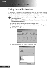
Wireless projection Using the audio function If "Wireless" is muted. Your audio driver may have different terminology for some of the projector. To set up the audio, you can also plug external speakers into the WPG's audio-out ...
Wireless projection Using the audio function If "Wireless" is muted. Your audio driver may have different terminology for some of the projector. To set up the audio, you can also plug external speakers into the WPG's audio-out ...


