

Service Guide
Page 4
... check the most up-to extend the functionality of customer machines. In such cases, please contact your Acer office may have decided to -date information available on card, modem, or extra memory capability). For ACER-AUTHORIZED SERVICE PROVIDERS, your regional offices or the responsible personnel/channel to those given in the printed Service... ORDERING FRU PARTS, that you with further technical details. 2. If, for repair and service of a machine (e.g. You MUST use the list provided by your regional Acer office to the BASIC CONFIGURATION decided for...
... check the most up-to extend the functionality of customer machines. In such cases, please contact your Acer office may have decided to -date information available on card, modem, or extra memory capability). For ACER-AUTHORIZED SERVICE PROVIDERS, your regional offices or the responsible personnel/channel to those given in the printed Service... ORDERING FRU PARTS, that you with further technical details. 2. If, for repair and service of a machine (e.g. You MUST use the list provided by your regional Acer office to the BASIC CONFIGURATION decided for...
Service Guide
Page 7
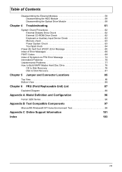
... 61 System Check Procedures 62 External Diskette Drive Check 62 External CD-ROM Drive Check 62 Keyboard or Auxiliary Input Device Check 62 Memory check 63 Power System Check 63 Touchpad check 64 Power-On Self-Test (POST) Error Message 65 Index of Error Messages 66... Top View 85 Bottom View 86 Chapter 6 FRU (Field Replaceable Unit) List 87 Exploded Diagram 88 Appendix A Model Definition and Configuration 96 Ferrari 3200 Series 96 Appendix B Test Compatible Components 97 Microsoft® Windows® XP Home Environment Test 98 Appendix C Online Support Information 101...
... 61 System Check Procedures 62 External Diskette Drive Check 62 External CD-ROM Drive Check 62 Keyboard or Auxiliary Input Device Check 62 Memory check 63 Power System Check 63 Touchpad check 64 Power-On Self-Test (POST) Error Message 65 Index of Error Messages 66... Top View 85 Bottom View 86 Chapter 6 FRU (Field Replaceable Unit) List 87 Exploded Diagram 88 Appendix A Model Definition and Configuration 96 Ferrari 3200 Series 96 Appendix B Test Compatible Components 97 Microsoft® Windows® XP Home Environment Test 98 Appendix C Online Support Information 101...
Service Guide
Page 8
Here are just a few of video memory 3D graphics engine Simultaneous LCD and CRT display support S-video for output to 1400X1050 Super eXtended ...mind. Chapter 1 System Specifications Features This computer was designed with 128MB of its many features: Performance T Mobile AMD AthlonTM 64 processor T Memory upgradeable up to 2GB DDR SDRAM with 2 slots (only one slot for user accessible) T High-capacity, Enhanced-IDE hard disk T...Bus) ports T IEEE 1394 port T Invilink 802.11g wireless LAN (manufacturing optional) T Bluetooth ready T SD/MMC/SM/MS memory slot Chapter 1 1 justmanuals.com
Here are just a few of video memory 3D graphics engine Simultaneous LCD and CRT display support S-video for output to 1400X1050 Super eXtended ...mind. Chapter 1 System Specifications Features This computer was designed with 128MB of its many features: Performance T Mobile AMD AthlonTM 64 processor T Memory upgradeable up to 2GB DDR SDRAM with 2 slots (only one slot for user accessible) T High-capacity, Enhanced-IDE hard disk T...Bus) ports T IEEE 1394 port T Invilink 802.11g wireless LAN (manufacturing optional) T Bluetooth ready T SD/MMC/SM/MS memory slot Chapter 1 1 justmanuals.com

Service Guide
Page 9
... Pointing Device T 84-/85-/88-key Windows keyboard T Sleek, smooth and stylish design T Acer FinTouch full-sized curved keyboard T Ergonomically-centered touchpad pointing device with four-way scroll button Expansion T T One type II CardBus PC Card slot Upgradeable memory I/O Ports T T T T T T T T T T T T T T T One Card bus type II slot One RJ-11 jack for 56Kbps... 2.0 ports One IEEE 1394 port One S-video (NTSC/PAL) output port 4-in-1 Card Reader (Manufacture optional) FIR (Fast Infred) port 100-pin expansion port supporting Acer EasyPort or I/O port replicator 2 Chapter 1
... Pointing Device T 84-/85-/88-key Windows keyboard T Sleek, smooth and stylish design T Acer FinTouch full-sized curved keyboard T Ergonomically-centered touchpad pointing device with four-way scroll button Expansion T T One type II CardBus PC Card slot Upgradeable memory I/O Ports T T T T T T T T T T T T T T T One Card bus type II slot One RJ-11 jack for 56Kbps... 2.0 ports One IEEE 1394 port One S-video (NTSC/PAL) output port 4-in-1 Card Reader (Manufacture optional) FIR (Fast Infred) port 100-pin expansion port supporting Acer EasyPort or I/O port replicator 2 Chapter 1
Service Guide
Page 14
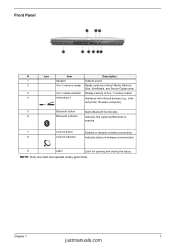
Front Panel # Icon Item Description 1 Speaker Outputs sound. 2 4-in-1 memory reader Reads cards from Smart Media, Memory Stick, MultiMedia, and Secure Digital cards. 3 4-in -1 memory reader. 4 Infrared port Interfaces with infrared devices (e.g., infra- red printer, IR-aware computer). 5 Bluetooth button Starts Bluetooth functionality. 6 Bluetooth indicator Indicates that (optional) Bluetooth is ...
Front Panel # Icon Item Description 1 Speaker Outputs sound. 2 4-in-1 memory reader Reads cards from Smart Media, Memory Stick, MultiMedia, and Secure Digital cards. 3 4-in -1 memory reader. 4 Infrared port Interfaces with infrared devices (e.g., infra- red printer, IR-aware computer). 5 Bluetooth button Starts Bluetooth functionality. 6 Bluetooth indicator Indicates that (optional) Bluetooth is ...
Service Guide
Page 18
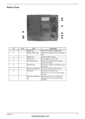
.... 5 Hard disk protector Protects the hard disk from accidental bumps and vibration. 6 Hard disk bay Houses the computer's hard disk (secured by a screw). 7 Memory compartment Houses th computer's main memory. 8 Cooling fan Helps keep the computer cool. Bottom Panel # Icon Item Description 1 Battery bay Houses the computer's battery pack. 2 Battery release latch...
.... 5 Hard disk protector Protects the hard disk from accidental bumps and vibration. 6 Hard disk bay Houses the computer's hard disk (secured by a screw). 7 Memory compartment Houses th computer's main memory. 8 Cooling fan Helps keep the computer cool. Bottom Panel # Icon Item Description 1 Battery bay Houses the computer's battery pack. 2 Battery release latch...

Service Guide
Page 29
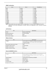
...cache control 2st level cache control Cache scheme control System Memory Item Memory controller Memory size DIMM socket number Supports memory size per socket Supports maximum memory size Supports DIMM type Supports DIMM Speed Supports DIMM voltage Supports DIMM package Memory module combinations Phneoix Specification Flash ROM 512KB PLCC ACPI 1....enabled Always enabled Fixed in write-back Specification Specification AMD Mobile AthlonTM 64 built-in 0MB (no on-board memory) 2 sockets 1024MB 2048MB (by two 1024MB SO-DIMM module) DDR Synchronous DRAM 333 MHz 2.5V 200-pin soDIMM You can install...
...cache control 2st level cache control Cache scheme control System Memory Item Memory controller Memory size DIMM socket number Supports memory size per socket Supports maximum memory size Supports DIMM type Supports DIMM Speed Supports DIMM voltage Supports DIMM package Memory module combinations Phneoix Specification Flash ROM 512KB PLCC ACPI 1....enabled Always enabled Fixed in write-back Specification Specification AMD Mobile AthlonTM 64 built-in 0MB (no on-board memory) 2 sockets 1024MB 2048MB (by two 1024MB SO-DIMM module) DDR Synchronous DRAM 333 MHz 2.5V 200-pin soDIMM You can install...
Service Guide
Page 30
... 1280MB 512MB 256MB 768MB 512MB 512MB 1024MB 512MB 1024MB 1536MB 1024MB 256MB 1280MB 1024MB 512MB 1536MB 1024MB 1024MB 2048MB NOTE: Above table lists some system memory configurations. Chapter 1 23 justmanuals.com LAN Interface Item Chipset Supports LAN protocol LAN connector type LAN connector location Modem Interface Item Chipset Data modem data...
... 1280MB 512MB 256MB 768MB 512MB 512MB 1024MB 512MB 1024MB 1536MB 1024MB 256MB 1280MB 1024MB 512MB 1536MB 1024MB 1024MB 2048MB NOTE: Above table lists some system memory configurations. Chapter 1 23 justmanuals.com LAN Interface Item Chipset Supports LAN protocol LAN connector type LAN connector location Modem Interface Item Chipset Data modem data...

Service Guide
Page 33
Video Interface Item Supports ZV (Zoomed Video) port Resolution Support Bus Specifications Memory Type VGA Ram Size Specification No Support for other devices. Yes (set by BIOS Setup IEEE 1394 Port Item Chipset Interface USB Compliancy Level Number ...
Video Interface Item Supports ZV (Zoomed Video) port Resolution Support Bus Specifications Memory Type VGA Ram Size Specification No Support for other devices. Yes (set by BIOS Setup IEEE 1394 Port Item Chipset Interface USB Compliancy Level Number ...
Service Guide
Page 41
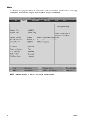
It allows the user to specify standard IBM PC AT system parameters. Shows system base memory size 522240 KB Shows extended memory size 128 MB VGA memory size [Enabled] [Auto ] [Enabled] [Enabled] [Disabled] F1 Help Esc Exit ↑ ↓ Select Item ← → Select Menu F5/F6 ...Values Enter Select 4 Sub-Menu NOTE: The screen above is for reference only. Main Advanced Security Boot Exit System Time: System Date: System Memory: Extended Memory: Video Memory Quiet Boot: Power on Display: LCD Auto Dim: Network Boot: F12 Boot Menu: Item Specific Help [14:06:58] [09/13/2004]...
It allows the user to specify standard IBM PC AT system parameters. Shows system base memory size 522240 KB Shows extended memory size 128 MB VGA memory size [Enabled] [Auto ] [Enabled] [Enabled] [Disabled] F1 Help Esc Exit ↑ ↓ Select Item ← → Select Menu F5/F6 ...Values Enter Select 4 Sub-Menu NOTE: The screen above is for reference only. Main Advanced Security Boot Exit System Time: System Date: System Memory: Extended Memory: Video Memory Quiet Boot: Power on Display: LCD Auto Dim: Network Boot: F12 Boot Menu: Item Specific Help [14:06:58] [09/13/2004]...
Service Guide
Page 42
.... NOTE: The sub-items under each device will not be in this screen. Chapter 2 35 justmanuals.com Extended Memory size=Total memory size-1MB Shows the VGA memory size. shows Summary Screen is set to 128MB Determines if Customer Logo will detect if any external display device is ... integrated LCD screen and the system's external video port (for an external CRT or projector). Parameter System Time System Date System Memory Extended Memory Video Memory Quiet Boot Power on external video port. This is because the user is fixed to control the settings in boldface are the...
.... NOTE: The sub-items under each device will not be in this screen. Chapter 2 35 justmanuals.com Extended Memory size=Total memory size-1MB Shows the VGA memory size. shows Summary Screen is set to 128MB Determines if Customer Logo will detect if any external display device is ... integrated LCD screen and the system's external video port (for an external CRT or projector). Parameter System Time System Date System Memory Extended Memory Video Memory Quiet Boot Power on external video port. This is because the user is fixed to control the settings in boldface are the...
Service Guide
Page 50
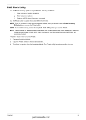
... run the Phlash utility. Then boot the system from the bootable diskette. The Phlash utility has auto-execution function. NOTE: Do not install memory-related drivers (XMS, EMS, DPMI) when you use the AC adaptor power supply when you may not boot the system because the BIOS ... conditions: T New versions of system programs T New features or options T Restore a BIOS when it becomes corrupted. BIOS Flash Utility The BIOS flash memory update is not completely loaded. NOTE: Please use the Phlash utility. Copy the Phlash utilities to update the system BIOS flash ROM. Chapter 2 43 ...
... run the Phlash utility. Then boot the system from the bootable diskette. The Phlash utility has auto-execution function. NOTE: Do not install memory-related drivers (XMS, EMS, DPMI) when you use the AC adaptor power supply when you may not boot the system because the BIOS ... conditions: T New versions of system programs T New features or options T Restore a BIOS when it becomes corrupted. BIOS Flash Utility The BIOS flash memory update is not completely loaded. NOTE: Please use the Phlash utility. Copy the Phlash utilities to update the system BIOS flash ROM. Chapter 2 43 ...
Service Guide
Page 54
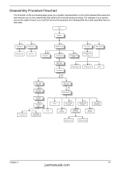
Start Battery Hx2 HDD Door Hx2 Dimm Door HDD Module Memory Hx2 Mx3 Keyboard Ox4 Middle Cover Sx4 LCD Module Hx3 Function Key Board Hx2 PCI Door ODD Module Wireless LAN Card Touchpad Main Unit Assembly ...
Start Battery Hx2 HDD Door Hx2 Dimm Door HDD Module Memory Hx2 Mx3 Keyboard Ox4 Middle Cover Sx4 LCD Module Hx3 Function Key Board Hx2 PCI Door ODD Module Wireless LAN Card Touchpad Main Unit Assembly ...

Service Guide
Page 63
... two screws holding the smart card reader then remove it . 17. Remove the modem/bluetooth combo card then disconnect the connector. 18. Pop out the memory then remove it . 56 Chapter 3 Disconnect the smart card reader FPC. 20. 13. Use a hex wrench (2.5mm) to fasten the CPU lock as shown. 16...
... two screws holding the smart card reader then remove it . 17. Remove the modem/bluetooth combo card then disconnect the connector. 18. Pop out the memory then remove it . 56 Chapter 3 Disconnect the smart card reader FPC. 20. 13. Use a hex wrench (2.5mm) to fasten the CPU lock as shown. 16...
Service Guide
Page 70
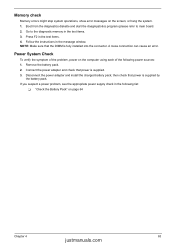
Boot from the diagnostics diskette and start the doagmpstotics program (please refer to the diagnostic memory in the following power sources: 1. Follow the instructions in the test items. 4. NOTE: Make sure that power is supplied by the battery pack. then ... A loose connection can cause an error. Go to main board. 2. Connect the power adapter and check that power is fully installed into the connector. Memory check Memory errors might stop system operations, show error messages on the computer using each of the problem, power on the screen, or hang the system. 1. Power...
Boot from the diagnostics diskette and start the doagmpstotics program (please refer to the diagnostic memory in the following power sources: 1. Follow the instructions in the test items. 4. NOTE: Make sure that power is supplied by the battery pack. then ... A loose connection can cause an error. Go to main board. 2. Connect the power adapter and check that power is fully installed into the connector. Memory check Memory errors might stop system operations, show error messages on the computer using each of the problem, power on the screen, or hang the system. 1. Power...

Service Guide
Page 72
If the symptom is listed first. NOTE: Most of memory installed. Some of them display information about a hardware device, e.g., the amount of the error messages occur during POST. The most likely cause is not listed, ...
If the symptom is listed first. NOTE: Most of memory installed. Some of them display information about a hardware device, e.g., the amount of the error messages occur during POST. The most likely cause is not listed, ...

Service Guide
Page 75
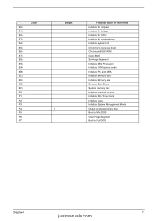
... POST values Restore CPU control word during warm boot Initialize PCI Bus Mastering devices Initialize keyboard controller BIOS ROM checksum Initialize cache before memory autosize 8254 timer initialization 8237 DMA controller initialization Reset Programmable Interrupt Controller Test DRAM refresh Test 8742 Keyboard Controller Set ES segment register ...to 4 GB Enable A20 line Autosize DRAM Initialize POST Memory Manager Clear 215 KB base RAM RAM failure on address line xxxx RAM failure on data bits xxxx of low byte of...
... POST values Restore CPU control word during warm boot Initialize PCI Bus Mastering devices Initialize keyboard controller BIOS ROM checksum Initialize cache before memory autosize 8254 timer initialization 8237 DMA controller initialization Reset Programmable Interrupt Controller Test DRAM refresh Test 8742 Keyboard Controller Set ES segment register ...to 4 GB Enable A20 line Autosize DRAM Initialize POST Memory Manager Clear 215 KB base RAM RAM failure on address line xxxx RAM failure on data bits xxxx of low byte of...

Service Guide
Page 76
... interrupts Initialize POST display service Display prompt "Press F2 to enter SETUP" Disable CPU cache Test RAM between 512 and 640 KB Test extended memory Test extended memory address lines Jump to User Patch1 Configure advanced cache registers Initialize Multi Processor APIC Enable external and CPU caches Setup System Management Mode (SMM...
... interrupts Initialize POST display service Display prompt "Press F2 to enter SETUP" Disable CPU cache Test RAM between 512 and 640 KB Test extended memory Test extended memory address lines Jump to User Patch1 Configure advanced cache registers Initialize Multi Processor APIC Enable external and CPU caches Setup System Management Mode (SMM...
Service Guide
Page 78
... boot Checksum BIOS ROM Go to BIOS Set Huge Segment Initialize Multi Processor Initialize OEM special code Initialize PIC and DMA Initialize Memory type Initialize Memory size Shadow Boot Block System memory test Initialize interrupt vectors Initialize Run Time Clock Initialize video Initialize System Management Mode Output one beep before boot Boot to...
... boot Checksum BIOS ROM Go to BIOS Set Huge Segment Initialize Multi Processor Initialize OEM special code Initialize PIC and DMA Initialize Memory type Initialize Memory size Shadow Boot Block System memory test Initialize interrupt vectors Initialize Run Time Clock Initialize video Initialize System Management Mode Output one beep before boot Boot to...

Service Guide
Page 80
... hang during POST Action in Sequence PCMCIA slot assembly Main board PCMCIA slot assembly Check if the PCMCIA slot is blocked Main board Memory-Related Symptoms Symptom / Error Memory count (size) appears different from the computer. Microphone cannot work Action in Sequence OS volume control Audio driver Speaker Main board Speaker Main...
... hang during POST Action in Sequence PCMCIA slot assembly Main board PCMCIA slot assembly Check if the PCMCIA slot is blocked Main board Memory-Related Symptoms Symptom / Error Memory count (size) appears different from the computer. Microphone cannot work Action in Sequence OS volume control Audio driver Speaker Main board Speaker Main...


