
AL2671W Service Guide
Page 23
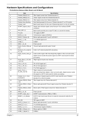
...the I/O module. 6 SCART_aspect_ratio_1 Aspect ratio indicator signal comes from pin-16 of ordinary SCART connector. 7 DAC_RST (1) Main board used this woofer signal to reset I2C DAC on current I/O module. 8 TX_232 'TX' signal of UART 9...Teletext_RGB_B_Retur 'Blue' signal return for Teletext decoder IC. re_L (2) 16 Audio_Center_Gnd_gn Audio woofer signal. Hardware Specifications and Configurations Pin Definition Between Main Board and I/O Board Item Specification 1 Teletext_RGB_B ( 6 ) 'Blue' signal comes from Teletext decoder IC. 2 Teletext_RGB_B ( 6 ) 'Green' signal ...
...the I/O module. 6 SCART_aspect_ratio_1 Aspect ratio indicator signal comes from pin-16 of ordinary SCART connector. 7 DAC_RST (1) Main board used this woofer signal to reset I2C DAC on current I/O module. 8 TX_232 'TX' signal of UART 9...Teletext_RGB_B_Retur 'Blue' signal return for Teletext decoder IC. re_L (2) 16 Audio_Center_Gnd_gn Audio woofer signal. Hardware Specifications and Configurations Pin Definition Between Main Board and I/O Board Item Specification 1 Teletext_RGB_B ( 6 ) 'Blue' signal comes from Teletext decoder IC. 2 Teletext_RGB_B ( 6 ) 'Green' signal ...
AL2671W Service Guide
Page 24
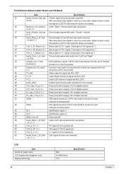
... ) Return path of ' Y ' signal. nal (2) After decoding Dolby digital or other surround audio, digital receiver sends this signal to LCDTV main board for further processing. 36 Earphone_for_subpictu Audio ' Right ' channel paired with audio ' Woofer ' channel. It belongs to YUV signal set -1. 40... ( 6 ) Return path of ' Pb ' signal. re_R ( 2 ) 37 Audio_Woofer_Gnd_gn Ground signal paired with sub-picture. Pin Definition Between Main Board and I /O modules 49 12V_max_1A_a ( 2 ) Power pins which supply +12V to digital receiver. 50 12V_max_1A_b ( 2 ) Power pins which supply...
... ) Return path of ' Y ' signal. nal (2) After decoding Dolby digital or other surround audio, digital receiver sends this signal to LCDTV main board for further processing. 36 Earphone_for_subpictu Audio ' Right ' channel paired with audio ' Woofer ' channel. It belongs to YUV signal set -1. 40... ( 6 ) Return path of ' Pb ' signal. re_R ( 2 ) 37 Audio_Woofer_Gnd_gn Ground signal paired with sub-picture. Pin Definition Between Main Board and I /O modules 49 12V_max_1A_a ( 2 ) Power pins which supply +12V to digital receiver. 50 12V_max_1A_b ( 2 ) Power pins which supply...

AL2671W Service Guide
Page 32
... the left). 2. Remove the ten screws that fasten the power board. 3. Remove the back cover. 3. Detach the wall mount assembly. Remove the three screws that fasten the back cover. 2. Removing the Back Cover and Wall ... mount assembly. 5. Remove another three screws holding power board. 46 Chapter 3 Remove four screw nuts holding the wall mount assembly. 4. Remove another five screws that secure the wall mount assembly. 7. Disconnect the cables (audio to power board; on the right/main board to power board; Remove the five screws holding the wall mount assembly...
... the left). 2. Remove the ten screws that fasten the power board. 3. Remove the back cover. 3. Detach the wall mount assembly. Remove the three screws that fasten the back cover. 2. Removing the Back Cover and Wall ... mount assembly. 5. Remove another three screws holding power board. 46 Chapter 3 Remove four screw nuts holding the wall mount assembly. 4. Remove another five screws that secure the wall mount assembly. 7. Disconnect the cables (audio to power board; on the right/main board to power board; Remove the five screws holding the wall mount assembly...
AL2671W Service Guide
Page 33
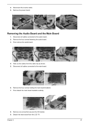
Remove the four screws fastening the audio board. 3. Chapter 3 47 Then remove the audio board. 4. Removing the Audio Board and the Main Board 1. 4. Disconnect the inverter cable. 5. Take out the cables from the LCD TV. Then detach the main board heatsink carefully. 8. Disconnect all cables connected to the main board. 6. Detach the main board from the cable clip as shown. 5. Disconnect all...
Remove the four screws fastening the audio board. 3. Chapter 3 47 Then remove the audio board. 4. Removing the Audio Board and the Main Board 1. 4. Disconnect the inverter cable. 5. Take out the cables from the LCD TV. Then detach the main board heatsink carefully. 8. Disconnect all cables connected to the main board. 6. Detach the main board from the cable clip as shown. 5. Disconnect all...
AL2671W Service Guide
Page 36
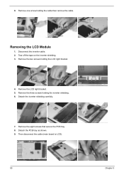
Removing the LCD Module 1. Then disconnect the cable (main board to LCD). 50 Chapter 3 Remove the LCD right bracket. 5. Detach the PCB tray as shown. 9. Tear off the tape on the inverter shielding. 3. Remove the two screws holding the cable then remove the cable. Remove the eight screws that secure the PCB tray. 8. Remove one screw holding the LCD right bracket. 4. Remove the three screws holding the inverter shielding. 6. Disconnect the inverter cable. 2. 9. Detach the inverter shielding carefully. 7.
Removing the LCD Module 1. Then disconnect the cable (main board to LCD). 50 Chapter 3 Remove the LCD right bracket. 5. Detach the PCB tray as shown. 9. Tear off the tape on the inverter shielding. 3. Remove the two screws holding the cable then remove the cable. Remove the eight screws that secure the PCB tray. 8. Remove one screw holding the LCD right bracket. 4. Remove the three screws holding the inverter shielding. 6. Disconnect the inverter cable. 2. 9. Detach the inverter shielding carefully. 7.
