Acer AC100 Service Guide
Page 2
...made on AC100S service guide. Intel and Xeon are registered trademarks of a machine (e.g. In such cases, please contact your regional web or channel. For ACER-AUTHORIZED SERVICE PROVIDERS, your regional Acer office to order FRU parts for Acer's "global" product offering. Any Acer Inc. ... chemical, manual or otherwise, without notice. Revision History Please refer to -date information available on card, modem, or extra memory capability). Acer is subject to the BASIC CONFIGURATION decided for repair and service of this generic service guide. All rights reserved. Should the ...
...made on AC100S service guide. Intel and Xeon are registered trademarks of a machine (e.g. In such cases, please contact your regional web or channel. For ACER-AUTHORIZED SERVICE PROVIDERS, your regional Acer office to order FRU parts for Acer's "global" product offering. Any Acer Inc. ... chemical, manual or otherwise, without notice. Revision History Please refer to -date information available on card, modem, or extra memory capability). Acer is subject to the BASIC CONFIGURATION decided for repair and service of this generic service guide. All rights reserved. Should the ...

Acer AC100 Service Guide
Page 5
...Access LED cables 27 Removing the Power Supply 28 Removing the Mainboard Tray 32 Removing the Heatsink 35 Removing the Processor 36 Removing the Memory Modules 38 Removing the Mainboard 38 Removing the RTC Battery 40 Removing the Expansion Slot Cover 41 Removing the Front I/O Board 41 Removing... the Front I/O Board 46 Reinstalling the Expansion Slot Cover 48 Replacing the RTC Battery 49 Replacing the Mainboard 49 Installing the Memory Modules 51 Reinstalling the Processor 52 Reinstalling the Heatsink 53 Reinstalling the Mainboard Tray 54 Reinstalling the Power Supply 56 v
...Access LED cables 27 Removing the Power Supply 28 Removing the Mainboard Tray 32 Removing the Heatsink 35 Removing the Processor 36 Removing the Memory Modules 38 Removing the Mainboard 38 Removing the RTC Battery 40 Removing the Expansion Slot Cover 41 Removing the Front I/O Board 41 Removing... the Front I/O Board 46 Reinstalling the Expansion Slot Cover 48 Replacing the RTC Battery 49 Replacing the Mainboard 49 Installing the Memory Modules 51 Reinstalling the Processor 52 Reinstalling the Heatsink 53 Reinstalling the Mainboard Tray 54 Reinstalling the Power Supply 56 v
Acer AC100 Service Guide
Page 11
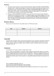
...System specifications Hardware specifications Items Processor socket Processor support Core logic chipsets Networking Media storage VGA controller I/O ports Memory Status LED indicators Thermal solution Software specifications Items Operating system Utilities Specifications LGA1155 • Intel E3-1260L &#...; Microsoft Windows Small Business Server • Red Hat Enterprise Linux 5 and 6 • SuSE Linux Enterprise Server • Acer ITSmart Add-in v1.0 • Power Scheduler • vPro Client Management • Fax Notification • Printer Management • Server Health ...
...System specifications Hardware specifications Items Processor socket Processor support Core logic chipsets Networking Media storage VGA controller I/O ports Memory Status LED indicators Thermal solution Software specifications Items Operating system Utilities Specifications LGA1155 • Intel E3-1260L &#...; Microsoft Windows Small Business Server • Red Hat Enterprise Linux 5 and 6 • SuSE Linux Enterprise Server • Acer ITSmart Add-in v1.0 • Power Scheduler • vPro Client Management • Fax Notification • Printer Management • Server Health ...

Acer AC100 Service Guide
Page 16
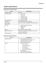
Internal components No. Component 1 Backplane board 2 Power supply 3 Memory module 4 Mainboard 5 System Fan 10 Chapter 3
Internal components No. Component 1 Backplane board 2 Power supply 3 Memory module 4 Mainboard 5 System Fan 10 Chapter 3

Acer AC100 Service Guide
Page 17
... the following states: • System failure • HDD failure • SATA controller failure • USB controller failure • LAN controller failure • Fan failure • Memory failure • Boot device not found Refer to "System Status Error Codes" on page 92 for BIOS update while boot block has been active) •...
... the following states: • System failure • HDD failure • SATA controller failure • USB controller failure • LAN controller failure • Fan failure • Memory failure • Boot device not found Refer to "System Status Error Codes" on page 92 for BIOS update while boot block has been active) •...

Acer AC100 Service Guide
Page 18
... connected to the power supply and turned on and ready for use. • System is booting • System is in S3 sleep state (suspend to memory) • System is not powered on. • System initialize operation in progress • System not initialized • HDD is not mounted into the drive bay...
... connected to the power supply and turned on and ready for use. • System is booting • System is in S3 sleep state (suspend to memory) • System is not powered on. • System initialize operation in progress • System not initialized • HDD is not mounted into the drive bay...

Acer AC100 Service Guide
Page 21
... power cable connector 12 3 CPU1 CPU socket 13 4 CN2 HDD access LED cable connector 14 5 CN1 Vcore power F/W update (reserved) 15 6 DIMM1A DDR3 memory slot 1 16 7 DIMM2A DDR3 memory slot 2 17 8 ATXCN1 24-pin power cable connector 18 9 CN17 PSU Information (reserved) 19 10 CN15 Front I/O board connector 20 Label CN14 PCIE1...
... power cable connector 12 3 CPU1 CPU socket 13 4 CN2 HDD access LED cable connector 14 5 CN1 Vcore power F/W update (reserved) 15 6 DIMM1A DDR3 memory slot 1 16 7 DIMM2A DDR3 memory slot 2 17 8 ATXCN1 24-pin power cable connector 18 9 CN17 PSU Information (reserved) 19 10 CN15 Front I/O board connector 20 Label CN14 PCIE1...

Acer AC100 Service Guide
Page 44
... clips on page 32. 2. See "Removing the Mainboard Tray" on both sides of the DIMM slot outward to release the DIMM (1). 3. If there is a second memory module installed, repeat steps 12 and 13 to remove it . Removing the Mainboard 1. Disconnect the front I/O cable connectors from the DIMM slot (2). 4. Please detach the...
... clips on page 32. 2. See "Removing the Mainboard Tray" on both sides of the DIMM slot outward to release the DIMM (1). 3. If there is a second memory module installed, repeat steps 12 and 13 to remove it . Removing the Mainboard 1. Disconnect the front I/O cable connectors from the DIMM slot (2). 4. Please detach the...

Acer AC100 Service Guide
Page 57
Installing the Memory Modules 1. Chapter 5 51 Disconnect the front I/O cable connectors to its mainboard connectors (CN14 and CN15). Insert the memory module into DIMM1A slot (1) and then press it down until it in DIMM2A slot by repeating step 1. 4. If a second memory module is available, install it clicks into place (2). 2.
Installing the Memory Modules 1. Chapter 5 51 Disconnect the front I/O cable connectors to its mainboard connectors (CN14 and CN15). Insert the memory module into DIMM1A slot (1) and then press it down until it in DIMM2A slot by repeating step 1. 4. If a second memory module is available, install it clicks into place (2). 2.

Acer AC100 Service Guide
Page 81
...sure the hardware is to check hardware problems. It executes simple tests of each diagnostic test and blinks red when an error condition occurs. Memory size check (1024 or 2048 MB) d. System Diagnosis Hardware diagnostic program The purpose of the hardware diagnostic program is not the source ...of the problem. PQAF memory test j. The indicator(s) blinks blue when the system has passed each hardware component to any USB port on the rear of the test ...
...sure the hardware is to check hardware problems. It executes simple tests of each diagnostic test and blinks red when an error condition occurs. Memory size check (1024 or 2048 MB) d. System Diagnosis Hardware diagnostic program The purpose of the hardware diagnostic program is not the source ...of the problem. PQAF memory test j. The indicator(s) blinks blue when the system has passed each hardware component to any USB port on the rear of the test ...
Acer AC100 Service Guide
Page 82
...the main POST Code Checkpoint. General Device Initialization (function 5). Function 5 configures all onboard peripherals that include manual configured onboard peripherals, memory and I/O decode windows in the Results folder.The name of the log file is based on ROM initialization for all remaining PnP...USB disk HDD 0 HDD 1 HDD 2 HDD 3 HDD 0 HDD 1 HDD 2 HDD 3 Backplane board temperature check PQAF system test PQAF memory test PQAF HDD test Read SN from 0 to initialize different BUSes. A copy of the serial number Device Initialization Manager code checkpoints The Device ...
...the main POST Code Checkpoint. General Device Initialization (function 5). Function 5 configures all onboard peripherals that include manual configured onboard peripherals, memory and I/O decode windows in the Results folder.The name of the log file is based on ROM initialization for all remaining PnP...USB disk HDD 0 HDD 1 HDD 2 HDD 3 HDD 0 HDD 1 HDD 2 HDD 3 Backplane board temperature check PQAF system test PQAF memory test PQAF HDD test Read SN from 0 to initialize different BUSes. A copy of the serial number Device Initialization Manager code checkpoints The Device ...

Acer AC100 Service Guide
Page 83
... after the flash update is booting System has booted HDD LED error codes 1 2 3 4 Description SATA controller failed USB controller failed LAN controller failed Fan failed Memory failed Boot device not found Disk failure BIOS Recovery Perform the BIOS recovery if the BIOS flash ROM has become corrupted. The following sections provide...
... after the flash update is booting System has booted HDD LED error codes 1 2 3 4 Description SATA controller failed USB controller failed LAN controller failed Fan failed Memory failed Boot device not found Disk failure BIOS Recovery Perform the BIOS recovery if the BIOS flash ROM has become corrupted. The following sections provide...
Acer AC100 Service Guide
Page 85
In this case, the system cannot retain configuration values in this utility. This memory area is not part of the system RAM which allows configuration data to run this guide. NOTE: AMI BIOS Setup Utility will need to be ... the Setup. Ask a qualified technician for assistance. The system reboots immediately after you have saved all open files. The screenshots used in a battery-backed nonvolatile memory called CMOS RAM. Since most systems are already properly configured and optimized, there is a hardware configuration program built into the system's Basic Input/Output System...
In this case, the system cannot retain configuration values in this utility. This memory area is not part of the system RAM which allows configuration data to run this guide. NOTE: AMI BIOS Setup Utility will need to be ... the Setup. Ask a qualified technician for assistance. The system reboots immediately after you have saved all open files. The screenshots used in a battery-backed nonvolatile memory called CMOS RAM. Since most systems are already properly configured and optimized, there is a hardware configuration program built into the system's Basic Input/Output System...

Acer AC100 Service Guide
Page 88
... core. Core speed of CPU installed on the system. Parameter System BIOS Version Build Date Processor Core Frequency Count Memory Size System Date System Time (hh:mm:ss) Description Version number of system memory installed on the system. Total size of the BIOS setup utility. Set the date following the hour-minute...
... core. Core speed of CPU installed on the system. Parameter System BIOS Version Build Date Processor Core Frequency Count Memory Size System Date System Time (hh:mm:ss) Description Version number of system memory installed on the system. Total size of the BIOS setup utility. Set the date following the hour-minute...

Acer AC100 Service Guide
Page 90
Memory Configuration This submenu displays the type and size of the memory installed in the system. Chipset Configuration 84 Chapter 7 the processor's type, frequency, core count and Cache L1, L2 settings.
Memory Configuration This submenu displays the type and size of the memory installed in the system. Chipset Configuration 84 Chapter 7 the processor's type, frequency, core count and Cache L1, L2 settings.

Acer AC100 Service Guide
Page 100
... setup. Discards all setup parameters. Loads the factory default settings for quitting the Setup Utility. Highlight any of resources consumption. Setup Defaults are using lowspeed memory chips or other kinds of low-performance components and you are quite demanding in terms of the exit options, then press . Discards changes made without...
... setup. Discards all setup parameters. Loads the factory default settings for quitting the Setup Utility. Highlight any of resources consumption. Setup Defaults are using lowspeed memory chips or other kinds of low-performance components and you are quite demanding in terms of the exit options, then press . Discards changes made without...

Acer AC100 Service Guide
Page 101
... be read and shown on an external monitor connected to the debug card. Chapter 8 95 If POST discovers errors in numeric coprocessor and cache memory subsystem • Direct memory access (DMA) controller (8237 module) • Interrupt system (8259 module) • Three programmable timers (system timer and 8254 module) • ROM subsystem •...
... be read and shown on an external monitor connected to the debug card. Chapter 8 95 If POST discovers errors in numeric coprocessor and cache memory subsystem • Direct memory access (DMA) controller (8237 module) • Interrupt system (8259 module) • Three programmable timers (system timer and 8254 module) • ROM subsystem •...

Acer AC100 Service Guide
Page 102
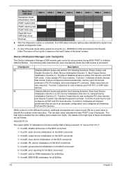
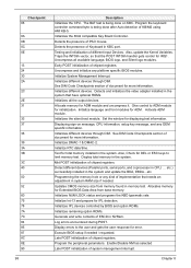
...is enabled. Give control to execute serial flash. An unique checkpoint number denotes each task. . If memory sizing module not executed, start memory refresh and do memory sizing in memory. Re-enable CACHE. Store the Uncompressed pointer for more information. 96 Chapter 8 Perform keyboard controller BAT...D2 D3 D4 D5 D6 D7 D8 D9 DA Description Early chipset initialization is done including RTC and keyboard controller. Execute full memory sizing module. Set stack. Early super I/O initialization is done. Save power-on CPUID value in PMM. Verify the bootblock ...
...is enabled. Give control to execute serial flash. An unique checkpoint number denotes each task. . If memory sizing module not executed, start memory refresh and do memory sizing in memory. Re-enable CACHE. Store the Uncompressed pointer for more information. 96 Chapter 8 Perform keyboard controller BAT...D2 D3 D4 D5 D6 D7 D8 D9 DA Description Early chipset initialization is done including RTC and keyboard controller. Execute full memory sizing module. Set stack. Early super I/O initialization is done. Save power-on CPUID value in PMM. Verify the bootblock ...
Acer AC100 Service Guide
Page 104
...Detects and initializes the video adapter installed in the system that the POST INT09h handler gets control for IRQ1. Give control to limit memory test. Initialize language and font modules for IPL detection. Also, Check for DEL or ESC keys to ADM module for more information..... Initializes the silent boot module. Set the window for ADM module and uncompress it. Displaying sign-on KBC. Allocates memory for error. Initializes IPL devices controlled by BIOS and option ROMs. Initializes remaining option ROMs. Generate and write contents of Keyboard in...
...Detects and initializes the video adapter installed in the system that the POST INT09h handler gets control for IRQ1. Give control to limit memory test. Initialize language and font modules for IPL detection. Also, Check for DEL or ESC keys to ADM module for more information..... Initializes the silent boot module. Set the window for ADM module and uncompress it. Displaying sign-on KBC. Allocates memory for error. Initializes IPL devices controlled by BIOS and option ROMs. Initializes remaining option ROMs. Generate and write contents of Keyboard in...
Acer AC100 Service Guide
Page 106
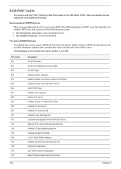
... left corner of error occurs during warm boot Initialize PCI Bus Mastering devices Initialize keyboard controller 1-2-2-3 BIOS ROM checksum Initialize cache before memory Auto size 8254 timer initialization 8237 DMA controller initialization Reset Programmable Interrupt Controller 100 Chapter 8 The following is a list of the ...following beep codes: • One long and two short beeps - no memory detected Terminal POST Errors If a terminal type of error occurs, BIOS will display an POST code that may also issue one of ...
... left corner of error occurs during warm boot Initialize PCI Bus Mastering devices Initialize keyboard controller 1-2-2-3 BIOS ROM checksum Initialize cache before memory Auto size 8254 timer initialization 8237 DMA controller initialization Reset Programmable Interrupt Controller 100 Chapter 8 The following is a list of the ...following beep codes: • One long and two short beeps - no memory detected Terminal POST Errors If a terminal type of error occurs, BIOS will display an POST code that may also issue one of ...
