
User Manual
Page 4
... 51 2.21.2 Installing Windows® VistaTM / VistaTM 64-bit Without RAID Functions 52 2.22 DTS Operation Guide 53 2.23 Untied Overclocking Technology 55 3 BIOS SETUP UTILITY 56 3.1 Introduction 56 3.1.1 BIOS Menu Bar 56 3.1.2 Navigation Keys 57 3.2 Main Screen 57 3.3 OC Tweaker Screen 58 3.4 Advanced Screen 61 3.4.1 CPU Configuration 62 3.4.2 Chipset Configuration 64...
... 51 2.21.2 Installing Windows® VistaTM / VistaTM 64-bit Without RAID Functions 52 2.22 DTS Operation Guide 53 2.23 Untied Overclocking Technology 55 3 BIOS SETUP UTILITY 56 3.1 Introduction 56 3.1.1 BIOS Menu Bar 56 3.1.2 Navigation Keys 57 3.2 Main Screen 57 3.3 OC Tweaker Screen 58 3.4 Advanced Screen 61 3.4.1 CPU Configuration 62 3.4.2 Chipset Configuration 64...

User Manual
Page 5
....4 cm) ASRock P55 Deluxe Quick Installation Guide ASRock P55 Deluxe Support CD 1 x 80-conductor Ultra ATA 66/100/133 IDE Ribbon Cable 1 x Ribbon Cable for purchasing ASRock P55 Deluxe motherboard, a reliable motherboard produced under ASRock's consistently stringent quality control. In case any modifications of the Support CD. It delivers excellent performance with robust design conforming to ASRock's commitment to BIOS setup and...
....4 cm) ASRock P55 Deluxe Quick Installation Guide ASRock P55 Deluxe Support CD 1 x 80-conductor Ultra ATA 66/100/133 IDE Ribbon Cable 1 x Ribbon Cable for purchasing ASRock P55 Deluxe motherboard, a reliable motherboard produced under ASRock's consistently stringent quality control. In case any modifications of the Support CD. It delivers excellent performance with robust design conforming to ASRock's commitment to BIOS setup and...

User Manual
Page 7
... x RJ-45 LAN Ports with LED (ACT/LINK LED and SPEED LED) - 1 x IEEE 1394 Port - 1 x Clear CMOS Switch with LED - 16Mb AMI BIOS - Front panel audio connector - 3 x USB 2.0 headers (support 6 USB 2.0 ports) (see CAUTION 8) - 1 x ATA133 IDE connector (supports 2 x IDE ... VCCM, SB, VTT Voltage Multi-adjustment - T. (Intelligent Overclocking Technology) - ACPI 1.1 Compliance Wake Up Events - Supports I. Supports Smart BIOS - AMI Legal BIOS - ASRock OC Tuner (see CAUTION 11) 7 Supports jumperfree - SMBIOS 2.3.1 Support - CD in /Front Speaker/Microphone (see CAUTION 7) - 6 x...
... x RJ-45 LAN Ports with LED (ACT/LINK LED and SPEED LED) - 1 x IEEE 1394 Port - 1 x Clear CMOS Switch with LED - 16Mb AMI BIOS - Front panel audio connector - 3 x USB 2.0 headers (support 6 USB 2.0 ports) (see CAUTION 8) - 1 x ATA133 IDE connector (supports 2 x IDE ... VCCM, SB, VTT Voltage Multi-adjustment - T. (Intelligent Overclocking Technology) - ACPI 1.1 Compliance Wake Up Events - Supports I. Supports Smart BIOS - AMI Legal BIOS - ASRock OC Tuner (see CAUTION 11) 7 Supports jumperfree - SMBIOS 2.3.1 Support - CD in /Front Speaker/Microphone (see CAUTION 7) - 6 x...

User Manual
Page 8
...at your system. For Windows® XP 64-bit and Windows® VistaTM 64-bit with overclocking, including adjusting the setting in the BIOS, applying Untied Overclocking Technology, or using the thirdparty overclocking tools. Hybrid Booster: - - Chassis Temperature Sensing - CAUTION! 1. For those... read the installation guide of memory modules on page 55 for system usage under Windows® XP and Windows® VistaTM. ASRock Instant Flash (see CAUTION 14) - CPU Temperature Sensing Monitor - Before you implement Dual Channel Memory Technology, make sure to ...
...at your system. For Windows® XP 64-bit and Windows® VistaTM 64-bit with overclocking, including adjusting the setting in the BIOS, applying Untied Overclocking Technology, or using the thirdparty overclocking tools. Hybrid Booster: - - Chassis Temperature Sensing - CAUTION! 1. For those... read the installation guide of memory modules on page 55 for system usage under Windows® XP and Windows® VistaTM. ASRock Instant Flash (see CAUTION 14) - CPU Temperature Sensing Monitor - Before you implement Dual Channel Memory Technology, make sure to ...

User Manual
Page 9
.... Frequencies other than the recommended CPU bus frequencies may cause the instability of ASRock OC Tuner. Power Management for the operation procedures of Intelligent Energy Saver. ASRock Instant Flash is a BIOS flash utility embedded in a few clicks without sacrificing computing performance. With this ...and mono modes. You can press key during the POST or press key to BIOS setup menu to adjust the settings after audio driver installation. ASRock website: http://www.asrock.com/feature/OCTuner/index.htm 11. Featuring an advanced proprietary hardware and software design...
.... Frequencies other than the recommended CPU bus frequencies may cause the instability of ASRock OC Tuner. Power Management for the operation procedures of Intelligent Energy Saver. ASRock Instant Flash is a BIOS flash utility embedded in a few clicks without sacrificing computing performance. With this ...and mono modes. You can press key during the POST or press key to BIOS setup menu to adjust the settings after audio driver installation. ASRock website: http://www.asrock.com/feature/OCTuner/index.htm 11. Featuring an advanced proprietary hardware and software design...

User Manual
Page 12
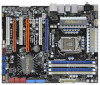
... MIC IN Top: LINE IN Center: FRONT PWR_FAN1 LAN PHY CPU_FAN1 P55 Deluxe PCIE1 CHA_FAN3 LAN PHY Dual GLAN PCI1 PCIE2 EuP Ready CMOS Battery CrossFireX 1394a Super I/O PCIE3 PCI Express 2.0 16Mb BIOS Intel P55 IDE1 SATAII_5_6 SATAII_3_4 SATAII_1_2 PCI2 RoHS AUDIO CODEC CD1 HD_AUDIO1 1 COM1...Jumper 22 Dr. Debug (LED) 2 ATX 12V Power Connector (ATX12V1) 23 USB 2.0 Header (USB8_9, Blue) 3 1156-Pin CPU Socket 24 Intel P55 Chipset 4 Chassis Fan Connector (CHA_FAN3) 25 Front Panel IEEE 1394 Header 5 2 x 240-pin DDR3 DIMM Slots (FRONT_1394, Red) (Dual Channel: DDR3_A2...
... MIC IN Top: LINE IN Center: FRONT PWR_FAN1 LAN PHY CPU_FAN1 P55 Deluxe PCIE1 CHA_FAN3 LAN PHY Dual GLAN PCI1 PCIE2 EuP Ready CMOS Battery CrossFireX 1394a Super I/O PCIE3 PCI Express 2.0 16Mb BIOS Intel P55 IDE1 SATAII_5_6 SATAII_3_4 SATAII_1_2 PCI2 RoHS AUDIO CODEC CD1 HD_AUDIO1 1 COM1...Jumper 22 Dr. Debug (LED) 2 ATX 12V Power Connector (ATX12V1) 23 USB 2.0 Header (USB8_9, Blue) 3 1156-Pin CPU Socket 24 Intel P55 Chipset 4 Chassis Fan Connector (CHA_FAN3) 25 Front Panel IEEE 1394 Header 5 2 x 240-pin DDR3 DIMM Slots (FRONT_1394, Red) (Dual Channel: DDR3_A2...

User Manual
Page 30
... Display feature. 2.9 Surround Display Feature This motherboard supports Surround Display upgrade. If no jumper cap is placed on PCI Express VGA cards, you update the BIOS. With the external add-on pins, the jumper is "Open". Clear CMOS Jumper (CLRCMOS1) (see p.12, No. 1) 2_3 Short pin2, pin3 to enable...the detailed instruction, please refer to clear the data in CMOS. If you need to clear the CMOS when you just finish updating the BIOS, you to the document at the following path in CMOS includes system setup information such as system password, date, time, and system setup parameters...
... Display feature. 2.9 Surround Display Feature This motherboard supports Surround Display upgrade. If no jumper cap is placed on PCI Express VGA cards, you update the BIOS. With the external add-on pins, the jumper is "Open". Clear CMOS Jumper (CLRCMOS1) (see p.12, No. 1) 2_3 Short pin2, pin3 to enable...the detailed instruction, please refer to clear the data in CMOS. If you need to clear the CMOS when you just finish updating the BIOS, you to the document at the following path in CMOS includes system setup information such as system password, date, time, and system setup parameters...

User Manual
Page 33
... Front Mic as default record device. If you use AC'97 audio panel, please install it to connect them for HD audio panel only. Enter BIOS Setup Utility. To activate the front mic. D. Set the Front Panel Control option from sound sources such as below: A. Connect Mic_IN (MIC) to install your...
... Front Mic as default record device. If you use AC'97 audio panel, please install it to connect them for HD audio panel only. Enter BIOS Setup Utility. To activate the front mic. D. Set the Front Panel Control option from sound sources such as below: A. Connect Mic_IN (MIC) to install your...

User Manual
Page 38
... sizing module not executed, start memory refresh and do memory sizing in scratch CMOS. Test base 512KB memory. Determine whether to BIOS POST (ExecutePOSTKernel). 38 The following table describes the type of checkpoints that may occur during the bootblock initialization portion of RAM. ...used to checkpoint E0. Save power-on CPUID value in Bootblock code. Verify that flat mode is forced. If BIOS recovery is enabled. Copying Main BIOS into register. Verify the bootblock checksum. Verify that flat mode is necessary, control flows to provide code information, ...
... sizing module not executed, start memory refresh and do memory sizing in scratch CMOS. Test base 512KB memory. Determine whether to BIOS POST (ExecutePOSTKernel). 38 The following table describes the type of checkpoints that may occur during the bootblock initialization portion of RAM. ...used to checkpoint E0. Save power-on CPUID value in Bootblock code. Verify that flat mode is forced. If BIOS recovery is enabled. Copying Main BIOS into register. Verify the bootblock checksum. Verify that flat mode is necessary, control flows to provide code information, ...

User Manual
Page 39
...Early POST initialization of Keyboard in KBC port. Allocate memory for initialization. Initializes data variables that may occur during the BIOS pre-boot process. Initializes both the 8259 compatible PICs in the Kernel Variable "wCMOSFlags." Program the keyboard controller command byte...for boot strap proccessor Early CPU Init Exit Initializes the 8042 compatible Key Board Controller. Uncompress and initialize any platform specific BIOS modules. Do R/W test to "POSTINT1ChHandlerBlock." Detects and initializes the video adapter installed in PIC for system timer interrupt....
...Early POST initialization of Keyboard in KBC port. Allocate memory for initialization. Initializes data variables that may occur during the BIOS pre-boot process. Initializes both the 8259 compatible PICs in the Kernel Variable "wCMOSFlags." Program the keyboard controller command byte...for boot strap proccessor Early CPU Init Exit Initializes the 8042 compatible Key Board Controller. Uncompress and initialize any platform specific BIOS modules. Do R/W test to "POSTINT1ChHandlerBlock." Detects and initializes the video adapter installed in PIC for system timer interrupt....

User Manual
Page 40
...through DIM. 39 Initializes DMAC-1 & DMAC-2. 3A Initialize RTC date/time. 3B Test for IPL detection. 78 Initializes IPL devices controlled by BIOS and option ROMs. 7A Initializes remaining option ROMs. 7C Generate and write contents of ESCD in memory test. Prepares the runtime language module....NVRam. 84 Log errors encountered during POST. 85 Display errors to the user and gets the user response for error. 87 Execute BIOS setup if needed before boot, which includes the programming of runtime image preparation for user input at config display if needed. AC ...
...through DIM. 39 Initializes DMAC-1 & DMAC-2. 3A Initialize RTC date/time. 3B Test for IPL detection. 78 Initializes IPL devices controlled by BIOS and option ROMs. 7A Initializes remaining option ROMs. 7C Generate and write contents of ESCD in memory test. Prepares the runtime language module....NVRam. 84 Log errors encountered during POST. 85 Display errors to the user and gets the user response for error. 87 Execute BIOS setup if needed before boot, which includes the programming of runtime image preparation for user input at config display if needed. AC ...

User Manual
Page 47
... data in it! A. When you see the message on the support CD driver page. Please insert a floppy diskette into the floppy drive. A. Enter BIOS SETUP UTILITY Advanced screen B. E. D. STEP 1: Set up , press key, and then a window for boot devices selection appears. Formatting the floppy diskette...will see these messages, Please insert a diskette into the floppy drive, and press . During POST at the beginning of system boot-up BIOS. Then, the drivers compatible to install those required drivers. Please follow the order from up to bottom side to your SATA / SATAII ...
... data in it! A. When you see the message on the support CD driver page. Please insert a floppy diskette into the floppy drive. A. Enter BIOS SETUP UTILITY Advanced screen B. E. D. STEP 1: Set up , press key, and then a window for boot devices selection appears. Formatting the floppy diskette...will see these messages, Please insert a diskette into the floppy drive, and press . During POST at the beginning of system boot-up BIOS. Then, the drivers compatible to install those required drivers. Please follow the order from up to bottom side to your SATA / SATAII ...

User Manual
Page 48
...", which is located in the Support CD, "Guide to your system as well. 2.20.2 Setting Up a "RAID Ready" System You can also set up system BIOS as step 2 of Windows® setup, press F6 to use "Intel Matrix Storage Manager" in Windows® environment, please install "SATAII driver" from the installation...
...", which is located in the Support CD, "Guide to your system as well. 2.20.2 Setting Up a "RAID Ready" System You can also set up system BIOS as step 2 of Windows® setup, press F6 to use "Intel Matrix Storage Manager" in Windows® environment, please install "SATAII driver" from the installation...

User Manual
Page 50
... If you want to use both "RAID Installation Guide" and "Intel Matrix Storage Manager Information" for proper configuration. STEP 1: Set up BIOS. Enter BIOS SETUP UTILITY Advanced screen Storage Configuration. 2.20.4 Installing Windows® VistaTM / VistaTM 64-bit With RAID Functions If you want to install... Windows® VistaTM / VistaTM 64-bit OS on the bottom to load the Intel® RAID drivers. B. page, please insert the ASRock Support CD into the optical drive to your system, and follow below steps. Intel® RAID drivers are allowed to use "Intel Matrix...
... If you want to use both "RAID Installation Guide" and "Intel Matrix Storage Manager Information" for proper configuration. STEP 1: Set up BIOS. Enter BIOS SETUP UTILITY Advanced screen Storage Configuration. 2.20.4 Installing Windows® VistaTM / VistaTM 64-bit With RAID Functions If you want to install... Windows® VistaTM / VistaTM 64-bit OS on the bottom to load the Intel® RAID drivers. B. page, please insert the ASRock Support CD into the optical drive to your system, and follow below steps. Intel® RAID drivers are allowed to use "Intel Matrix...

User Manual
Page 51
... below steps. Windows XP/2000" for Windows® XP 64-bit. After making a SATA / SATAII driver diskette, you install. Enter BIOS SETUP UTILITY Advanced screen Storage Configuration. At the beginning of Windows® setup, press F6 to install Windows® XP / XP 64-bit... driver will be presented. Set the option "SATAII Operation Mode" to [AHCI]. Using SATA / SATAII HDDs with NCQ function STEP 1: Set Up BIOS. Enter BIOS SETUP UTILITY Advanced screen Storage Configuration. B. Set the option "SATAII Operation Mode" to [IDE]. Please make a SATA / SATAII driver diskette by...
... below steps. Windows XP/2000" for Windows® XP 64-bit. After making a SATA / SATAII driver diskette, you install. Enter BIOS SETUP UTILITY Advanced screen Storage Configuration. At the beginning of Windows® setup, press F6 to install Windows® XP / XP 64-bit... driver will be presented. Set the option "SATAII Operation Mode" to [AHCI]. Using SATA / SATAII HDDs with NCQ function STEP 1: Set Up BIOS. Enter BIOS SETUP UTILITY Advanced screen Storage Configuration. B. Set the option "SATAII Operation Mode" to [IDE]. Please make a SATA / SATAII driver diskette by...

User Manual
Page 52
...SATA / SATAII HDDs without RAID functions, please follow the instruction to install Windows® VistaTM / VistaTM 64-bit OS on your system. A. B. Enter BIOS SETUP UTILITY Advanced screen Storage Configuration. STEP 2: Install Windows® VistaTM / VistaTM 64-bit OS on your system. 52 Enter...® VistaTM / VistaTM 64-bit OS on your system. When you see "Where do you want to install Windows?" page, please insert the ASRock Support CD into the optical drive to boot your system, and follow below steps. Intel® AHCI drivers are in the following path in our...
...SATA / SATAII HDDs without RAID functions, please follow the instruction to install Windows® VistaTM / VistaTM 64-bit OS on your system. A. B. Enter BIOS SETUP UTILITY Advanced screen Storage Configuration. STEP 2: Install Windows® VistaTM / VistaTM 64-bit OS on your system. 52 Enter...® VistaTM / VistaTM 64-bit OS on your system. When you see "Where do you want to install Windows?" page, please insert the ASRock Support CD into the optical drive to boot your system, and follow below steps. Intel® AHCI drivers are in the following path in our...

User Manual
Page 55
... [Manual]. Please refer to the warning on page 8 for the possible overclocking risk before you enable Untied Overclocking function, please enter "Overclock Mode" option of BIOS setup to set the selection from [Auto] to fixed PCI / PCIE buses. 2.23 Untied Overclocking Technology This motherboard supports Untied Overclocking Technology, which means during...
... [Manual]. Please refer to the warning on page 8 for the possible overclocking risk before you enable Untied Overclocking function, please enter "Overclock Mode" option of BIOS setup to set the selection from [Auto] to fixed PCI / PCIE buses. 2.23 Untied Overclocking Technology This motherboard supports Untied Overclocking Technology, which means during...

User Manual
Page 56
...to locate and load the Operating System Security To set up the default system device to get into the sub screen. 56 Because the BIOS software is constantly being updated, the following selections: Main To set up the system time/date information OC Tweaker To set up overclocking ...features Advanced To set up the advanced BIOS features H/W Monitor To display current hardware status Boot To set up the computer. If you start up the security features Exit To exit ...
...to locate and load the Operating System Security To set up the default system device to get into the sub screen. 56 Because the BIOS software is constantly being updated, the following selections: Main To set up the system time/date information OC Tweaker To set up overclocking ...features Advanced To set up the advanced BIOS features H/W Monitor To display current hardware status Boot To set up the computer. If you start up the security features Exit To exit ...

User Manual
Page 57
... Main OC Tweaker Advanced H/W Monitor Boot Security Exit System Overview System Time System Date [14:00:09] [Thu 06/04/2009] BIOS Version : P55 Deluxe P1.00 Processor Type : Intel (R) Core (TM) CPU 860 @ 2.80GHz (64bit) Processor Speed : 2800MHz Microcode Update : 106E5/3 Cache Size : 8192KB Total Memory DDR3_A2 DDR3_A1...54 (C) Copyright 1985-2005, American Megatrends, Inc. 3.1.2Navigation Keys Please check the following table for all the settings To save changes and exit the BIOS SETUP UTILITY To jump to the Exit Screen or exit the current screen 3.2 Main Screen When you enter the...
... Main OC Tweaker Advanced H/W Monitor Boot Security Exit System Overview System Time System Date [14:00:09] [Thu 06/04/2009] BIOS Version : P55 Deluxe P1.00 Processor Type : Intel (R) Core (TM) CPU 860 @ 2.80GHz (64bit) Processor Speed : 2800MHz Microcode Update : 106E5/3 Cache Size : 8192KB Total Memory DDR3_A2 DDR3_A1...54 (C) Copyright 1985-2005, American Megatrends, Inc. 3.1.2Navigation Keys Please check the following table for all the settings To save changes and exit the BIOS SETUP UTILITY To jump to the Exit Screen or exit the current screen 3.2 Main Screen When you enter the...

User Manual
Page 58
...], [3.90GHz], [4.00GHz] and [4.20GHz]. Configuration options: [Auto], [Manual], [I .O.T.] (Intelligent Overclocking Technology), the system will automatically enable the overclocking function when your own risk and expense. BIOS SETUP UTILITY Main OC Tweaker Advanced H/W Monitor Boot Security Exit OC Tweaker Settings Load CPU EZ OC Setting Load Memory EZ OC Setting Overclock Mode...
...], [3.90GHz], [4.00GHz] and [4.20GHz]. Configuration options: [Auto], [Manual], [I .O.T.] (Intelligent Overclocking Technology), the system will automatically enable the overclocking function when your own risk and expense. BIOS SETUP UTILITY Main OC Tweaker Advanced H/W Monitor Boot Security Exit OC Tweaker Settings Load CPU EZ OC Setting Load Memory EZ OC Setting Overclock Mode...


