
User Manual
Page 4
... Configuration 46 3.4.4 IDE Configuration 47 3.4.5 PCIPnP Configuration 49 3.4.6 Floppy Configuration 50 3.4.7 Super IO Configuration 50 3.4.8 USB Configuration 52 3.5 Hardware Health Event Monitoring Screen 53 3.6 Boot Screen 54 3.6.1 Boot Settings Configuration 54 3.7 Security Screen 55 3.8 Exit Screen 56 4 . Software Support 57 4.1 Install Operating System 57 4.2 Support CD Information 57 4.2.1 Running Support CD 57...
... Configuration 46 3.4.4 IDE Configuration 47 3.4.5 PCIPnP Configuration 49 3.4.6 Floppy Configuration 50 3.4.7 Super IO Configuration 50 3.4.8 USB Configuration 52 3.5 Hardware Health Event Monitoring Screen 53 3.6 Boot Screen 54 3.6.1 Boot Settings Configuration 54 3.7 Security Screen 55 3.8 Exit Screen 56 4 . Software Support 57 4.1 Install Operating System 57 4.2 Support CD Information 57 4.2.1 Running Support CD 57...
User Manual
Page 7
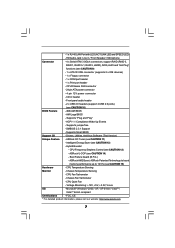
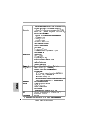
...Fan - CPU/Chassis FAN connector - 24 pin ATX power connector - 4 pin 12V power connector - Chassis Temperature Sensing - AMI Legal BIOS - ASRock OC Tuner (see CAUTION 10) BIOS Feature - 4Mb AMI BIOS - Microsoft® Windows® 2000 / XP / XP 64-bit / ...Drivers, Utilities, AntiVirus Software (Trial Version) Unique Feature - Intelligent Energy Saver (see CAUTION 15) Hardware - Boot Failure Guard (B.F.G.) - ASRock AM2 Boost: ASRock Patented Technology to boost memory performance up to 12.5% (see CAUTION 12) - Voltage Monitoring: +12V, +5V, +3.3V, Vcore OS -
...Fan - CPU/Chassis FAN connector - 24 pin ATX power connector - 4 pin 12V power connector - Chassis Temperature Sensing - AMI Legal BIOS - ASRock OC Tuner (see CAUTION 10) BIOS Feature - 4Mb AMI BIOS - Microsoft® Windows® 2000 / XP / XP 64-bit / ...Drivers, Utilities, AntiVirus Software (Trial Version) Unique Feature - Intelligent Energy Saver (see CAUTION 15) Hardware - Boot Failure Guard (B.F.G.) - ASRock AM2 Boost: ASRock Patented Technology to boost memory performance up to 12.5% (see CAUTION 12) - Voltage Monitoring: +12V, +5V, +3.3V, Vcore OS -

User Manual
Page 18
... will be displayed only in one of the two monitors instead of this motherboard. If you can start to your system and restart your system boots.
... will be displayed only in one of the two monitors instead of this motherboard. If you can start to your system and restart your system boots.
User Manual
Page 19
... the Display Properties dialog that you can easily enjoy the benefits of the system memory. C. Right-click the display icon and select "Attached", if necessary. Boot your system. Set up a surround display environment: 1. Set the "Screen Resolution" and "Color Quality" as Secondary. For Windows® 2000 / XP / XP 64-bit OS...
... the Display Properties dialog that you can easily enjoy the benefits of the system memory. C. Right-click the display icon and select "Attached", if necessary. Boot your system. Set up a surround display environment: 1. Set the "Screen Resolution" and "Color Quality" as Secondary. For Windows® 2000 / XP / XP 64-bit OS...

User Manual
Page 22
.... If no jumper cap is placed on these 2 pins. If you need to clear the CMOS when you just finish updating the BIOS, you must boot up events.
.... If no jumper cap is placed on these 2 pins. If you need to clear the CMOS when you just finish updating the BIOS, you must boot up events.
User Manual
Page 31
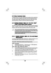
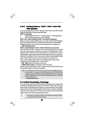
...174; 2000 / XP / XP 64-bit / VistaTM / VistaTM 64-bit Without RAID Functions If you see the message on your system. (There are two ASRock Support CD in your optical drive first. A. Set the "SATA Operation Mode" option to include SP4. STEP 2: Make a SATA / SATAII driver diskette. ...your system, your Windows® 2000optical disk is no SP4 included in the motherboard gift box pack, please choose the one for boot devices selection appears. B. Insert the ASRock Support CD into your optical drive to install Windows® 2000 / Windows® XP / Windows® XP 64-bit on...
...174; 2000 / XP / XP 64-bit / VistaTM / VistaTM 64-bit Without RAID Functions If you see the message on your system. (There are two ASRock Support CD in your optical drive first. A. Set the "SATA Operation Mode" option to include SP4. STEP 2: Make a SATA / SATAII driver diskette. ...your system, your Windows® 2000optical disk is no SP4 included in the motherboard gift box pack, please choose the one for boot devices selection appears. B. Insert the ASRock Support CD into your optical drive to install Windows® 2000 / Windows® XP / Windows® XP 64-bit on...

User Manual
Page 33
... Enter BIOS SETUP UTILITY Advanced screen IDE Configuration. Insert the Windows® VistaTM / Windows® VistaTM 64-bit optical disk into the optical drive to boot your system, and follow below website for Windows® VistaTM / VistaTM 64-bit.) .. \ I386 \ AHCI_Vista (For Windows® VistaTM OS) ....."SATA Operation Mode" option to continue the installation. If there is supposed to [AHCI]. STEP 1: Set Up BIOS. page, please insert the ASRock Support CD into the optical drive again to [IDE]. STEP 2: Install Windows® VistaTM / VistaTM 64-bit OS on your disk, please...
... Enter BIOS SETUP UTILITY Advanced screen IDE Configuration. Insert the Windows® VistaTM / Windows® VistaTM 64-bit optical disk into the optical drive to boot your system, and follow below website for Windows® VistaTM / VistaTM 64-bit.) .. \ I386 \ AHCI_Vista (For Windows® VistaTM OS) ....."SATA Operation Mode" option to continue the installation. If there is supposed to [AHCI]. STEP 1: Set Up BIOS. page, please insert the ASRock Support CD into the optical drive again to [IDE]. STEP 2: Install Windows® VistaTM / VistaTM 64-bit OS on your disk, please...
User Manual
Page 35
... Support CD: .. \ RAID Installation Guide 2.16 Untied Overclocking Technology This motherboard supports Untied Overclocking Technology, which means during overclocking, but PCI / PCIE buses are two ASRock Support CD in the fixed mode so that , please insert Windows® VistaTM / Windows® VistaTM 64-bit optical disk into the optical drive again... 64-bit on your SATA / SATAII HDDs with RAID functions, please follow the instruction to load the NVIDIA® RAID drivers. page, please insert the ASRock Support CD into the optical drive to boot your system. NOTE.
... Support CD: .. \ RAID Installation Guide 2.16 Untied Overclocking Technology This motherboard supports Untied Overclocking Technology, which means during overclocking, but PCI / PCIE buses are two ASRock Support CD in the fixed mode so that , please insert Windows® VistaTM / Windows® VistaTM 64-bit optical disk into the optical drive again... 64-bit on your SATA / SATAII HDDs with RAID functions, please follow the instruction to load the NVIDIA® RAID drivers. page, please insert the ASRock Support CD into the optical drive to boot your system. NOTE.

User Manual
Page 36
... following selections: Main To set up the system time/date information Advanced To set up the advanced BIOS features H/W Monitor To display current hardware status Boot To set up the default system device to locate and load the Operating System Security To set up the computer. 3. The Flash Memory on the...
... following selections: Main To set up the system time/date information Advanced To set up the advanced BIOS features H/W Monitor To display current hardware status Boot To set up the default system device to locate and load the Operating System Security To set up the computer. 3. The Flash Memory on the...

User Manual
Page 37
.../Year] Use this item to specify the system date. 37 BIOS SETUP UTILITY Main Smart Advanced H/W Monitor Boot Security Exit System Overview System Time System Date [14:00:09] [Tue 09/02/2008] BIOS Version : N68PV-GS P1.00 Processor Type : AMD Athlon(tm) Dual Core Processor 4450e (64bit) Processor Speed : 2300MHz Microcode...
.../Year] Use this item to specify the system date. 37 BIOS SETUP UTILITY Main Smart Advanced H/W Monitor Boot Security Exit System Overview System Time System Date [14:00:09] [Tue 09/02/2008] BIOS Version : N68PV-GS P1.00 Processor Type : AMD Athlon(tm) Dual Core Processor 4450e (64bit) Processor Speed : 2300MHz Microcode...

User Manual
Page 38
F10 key can be used for this operation. Save Changes and Exit When you can be compatible with all the setup questions. If system boot failure occurs after loading, please resume optimal default settings. F3 key can load the BIOS setup according to your requirements. Load Performance Setup... Item Enter Go to save the changes and exit the BIOS SETUP UTILITY. Load BIOS Defaults Load BIOS default values for this operation. If system boot failure occurs after saving the changes. 3.3 Smart Screen In the Smart screen, you select this operation. Select [OK] to Sub Screen F1 General...
F10 key can be used for this operation. Save Changes and Exit When you can be compatible with all the setup questions. If system boot failure occurs after loading, please resume optimal default settings. F3 key can load the BIOS setup according to your requirements. Load Performance Setup... Item Enter Go to save the changes and exit the BIOS SETUP UTILITY. Load BIOS Defaults Load BIOS default values for this operation. If system boot failure occurs after saving the changes. 3.3 Smart Screen In the Smart screen, you select this operation. Select [OK] to Sub Screen F1 General...
User Manual
Page 39
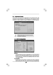
... rated frequency/voltage. 3.4 Advanced Screen In this section may cause the system to select Overclock Mode. If you will enable ASRock AM2 Boost function, which will be set the configurations for the following items: CPU Configuration, Chipset Configuration, ACPI Configuration, IDE...AM2 Boost Overclock Mode CPU Frequency (MHz) PCIE Frequency (MHz) CPU/LDT Spread Spectrum PCIE Spread Spectrum SATA Spread Spectrum Boot Failure Guard Cool' n' Quiet Secure Virtual Machine Enhanced Halt State Processor Maximum Frequency Processor Maximum Voltage Multiplier/Voltage Change Memory Clock...
... rated frequency/voltage. 3.4 Advanced Screen In this section may cause the system to select Overclock Mode. If you will enable ASRock AM2 Boost function, which will be set the configurations for the following items: CPU Configuration, Chipset Configuration, ACPI Configuration, IDE...AM2 Boost Overclock Mode CPU Frequency (MHz) PCIE Frequency (MHz) CPU/LDT Spread Spectrum PCIE Spread Spectrum SATA Spread Spectrum Boot Failure Guard Cool' n' Quiet Secure Virtual Machine Enhanced Halt State Processor Maximum Frequency Processor Maximum Voltage Multiplier/Voltage Change Memory Clock...

User Manual
Page 40
...Maximum Frequency This option appears only when you adopt AM2 CPU. Processor Maximum Voltage It will display Processor Maximum Frequency for reference. Boot Failure Guard Enable or disable the feature of the system caches. The default value is [Enabled]. Please set to [Disable] ... [Disabled] and [Enabled]. Configuration options: [Auto], [Enabled] and [Disabled]. In the C1 power state, the processor maintains the context of Boot Failure Guard. If you install Windows® VistaTM and want to enable this function, please set to [Enabled]. Secure Virtual Machine This option appears...
...Maximum Frequency This option appears only when you adopt AM2 CPU. Processor Maximum Voltage It will display Processor Maximum Frequency for reference. Boot Failure Guard Enable or disable the feature of the system caches. The default value is [Enabled]. Please set to [Disable] ... [Disabled] and [Enabled]. Configuration options: [Auto], [Enabled] and [Disabled]. In the C1 power state, the processor maintains the context of Boot Failure Guard. If you install Windows® VistaTM and want to enable this function, please set to [Enabled]. Secure Virtual Machine This option appears...

User Manual
Page 41
... SETUP UTILITY Advanced CPU Configuration AM2 Boost Overclock Mode CPU Frequency (MHz) PCIE Frequency (MHz) CPU/LDT Spread Spectrum PCIE Spread Spectrum SATA Spread Spectrum Boot Failure Guard Cool' n' Quiet Secure Virtual Machine Enhanced Halt State Processor Maximum Frequency Processor Maximum Voltage Multiplier/Voltage Change Processor Frequency Processor Voltage [Disabled] [Auto...
... SETUP UTILITY Advanced CPU Configuration AM2 Boost Overclock Mode CPU Frequency (MHz) PCIE Frequency (MHz) CPU/LDT Spread Spectrum PCIE Spread Spectrum SATA Spread Spectrum Boot Failure Guard Cool' n' Quiet Secure Virtual Machine Enhanced Halt State Processor Maximum Frequency Processor Maximum Voltage Multiplier/Voltage Change Processor Frequency Processor Voltage [Disabled] [Auto...

User Manual
Page 46
... whether to auto-detect or disable the Suspend-to-RAM feature. PS/2 Keyboard Power On Use this item to enable or disable PS/2 keyboard to boot up when the power recovers.
... whether to auto-detect or disable the Suspend-to-RAM feature. PS/2 Keyboard Power On Use this item to enable or disable PS/2 keyboard to boot up when the power recovers.

User Manual
Page 53
... section, it allows you set this option as [Enabled], you will be between 45 C/113 F and 65 C/149 F. BIOS SETUP UTILITY Main Smart Advanced H/W Monitor Boot Security Exit Hardware Health Event Monitoring CPU Temperature M / B Temperature CPU Fan Speed Chassis Fan Speed Vcore + 3.30V + 5.00V + 12.00V : 37 C / 98 F : 31 C / 87 F : 3400...
... section, it allows you set this option as [Enabled], you will be between 45 C/113 F and 65 C/149 F. BIOS SETUP UTILITY Main Smart Advanced H/W Monitor Boot Security Exit Hardware Health Event Monitoring CPU Temperature M / B Temperature CPU Fan Speed Chassis Fan Speed Vcore + 3.30V + 5.00V + 12.00V : 37 C / 98 F : 31 C / 87 F : 3400...

User Manual
Page 54
...this section, it will display the available devices on your system for you want to [On], it will automatically activate the Numeric Lock function after boot-up. 54 The default value is [Enabled]. Configuration options: [Enabled] and [Disabled]. AddOn ROM Display Use this item is set to see the... General Help Load Defaults Save and Exit Exit v02.54 (C) Copyright 1985-2003, American Megatrends, Inc. CD - The default value is [Enabled]. Boot From Onboard LAN Use this item to Sub Screen F1 General Help F9 Load Defaults F10 Save and Exit ESC Exit v02.54 (C) Copyright 1985...
...this section, it will display the available devices on your system for you want to [On], it will automatically activate the Numeric Lock function after boot-up. 54 The default value is [Enabled]. Configuration options: [Enabled] and [Disabled]. AddOn ROM Display Use this item is set to see the... General Help Load Defaults Save and Exit Exit v02.54 (C) Copyright 1985-2003, American Megatrends, Inc. CD - The default value is [Enabled]. Boot From Onboard LAN Use this item to Sub Screen F1 General Help F9 Load Defaults F10 Save and Exit ESC Exit v02.54 (C) Copyright 1985...

User Manual
Page 55
For the user password, you may also clear it. BIOS SETUP UTILITY Main Smart Advanced H/W Monitor Boot Security Exit Security Settings Supervisor Password : Not Installed User Password : Not Installed Change Supervisor Password Change User Password Install or Change the password. Select Screen Select Item Enter Change F1 General Help F9 Load Defaults F10 Save and Exit ESC Exit v02.54 (C) Copyright 1985-2005, American Megatrends, Inc. 55 3.7 Security Screen In this section, you may set or change the supervisor/user password for the system.
For the user password, you may also clear it. BIOS SETUP UTILITY Main Smart Advanced H/W Monitor Boot Security Exit Security Settings Supervisor Password : Not Installed User Password : Not Installed Change Supervisor Password Change User Password Install or Change the password. Select Screen Select Item Enter Change F1 General Help F9 Load Defaults F10 Save and Exit ESC Exit v02.54 (C) Copyright 1985-2005, American Megatrends, Inc. 55 3.7 Security Screen In this section, you may set or change the supervisor/user password for the system.

User Manual
Page 56
... Load Defaults F10 Save and Exit ESC Exit v02.54 (C) Copyright 1985-2005, American Megatrends, Inc. 3.8 Exit Screen BIOS SETUP UTILITY Main Smart Advanced H/W Monitor Boot Security Exit Exit Options Save Changes and Exit Discard Changes and Exit Discard Changes Would you like to save current setting user defaults ? Select [OK...
... Load Defaults F10 Save and Exit ESC Exit v02.54 (C) Copyright 1985-2005, American Megatrends, Inc. 3.8 Exit Screen BIOS SETUP UTILITY Main Smart Advanced H/W Monitor Boot Security Exit Exit Options Save Changes and Exit Discard Changes and Exit Discard Changes Would you like to save current setting user defaults ? Select [OK...
Quick Installation Guide
Page 6
...connector - 1 x COM port header - 1 x Print port header - Boot Failure Guard (B.F.G.) - CPU Temperature Sensing Monitor - Front panel audio header - 2 x USB 2.0 headers (support 4 USB 2.0 ports) (see CAUTION 15) Hardware - ASRock OC Tuner (see CAUTION 13) - CPU Frequency Stepless Control (see CAUTION... pin 12V power connector - ASRock U-COP (see CAUTION 12) - Chassis Fan Tachometer - Chassis Temperature Sensing - FCC, CE * For detailed product information, please visit our website: http://www.asrock.com English 6 ASRock N68PV-GS Motherboard - 1 x RJ-...
...connector - 1 x COM port header - 1 x Print port header - Boot Failure Guard (B.F.G.) - CPU Temperature Sensing Monitor - Front panel audio header - 2 x USB 2.0 headers (support 4 USB 2.0 ports) (see CAUTION 15) Hardware - ASRock OC Tuner (see CAUTION 13) - CPU Frequency Stepless Control (see CAUTION... pin 12V power connector - ASRock U-COP (see CAUTION 12) - Chassis Fan Tachometer - Chassis Temperature Sensing - FCC, CE * For detailed product information, please visit our website: http://www.asrock.com English 6 ASRock N68PV-GS Motherboard - 1 x RJ-...

