
User Manual
Page 6
... non-ECC, un-buffered memory (see CAUTION 1) - Integrated NVIDIA® GeForce7 Series (NV44) - Micro ATX Form Factor: 9.6-in x 7.2-in, 24.4 cm x 18.3 cm - Support for Socket AM2+ / AM2 processors: AMD PhenomTM FX / Phenom / Athlon 64 FX / Athlon 64 X2 Dual-Core / Athlon X2 Dual-Core / Athlon 64 / Sempron processor (see CAUTION 4) -
... non-ECC, un-buffered memory (see CAUTION 1) - Integrated NVIDIA® GeForce7 Series (NV44) - Micro ATX Form Factor: 9.6-in x 7.2-in, 24.4 cm x 18.3 cm - Support for Socket AM2+ / AM2 processors: AMD PhenomTM FX / Phenom / Athlon 64 FX / Athlon 64 X2 Dual-Core / Athlon X2 Dual-Core / Athlon 64 / Sempron processor (see CAUTION 4) -

User Manual
Page 12
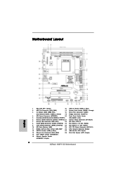
... Mouse PS2 Keyboard 1 PS2_USB_PW1 DDRII_2 (64 bit, 240-pFinSmBod8u0le0) 3 DDRII_1 (64 bit, 240-pin module) DVI_CON1 DDR2 1066 Dual Channel AM2+ CPU_FAN1 4 28 SOCKET AM2 LPT1 1 Super I/O ATXPWR1 24.4cm (9.6-in) VGA1 27 26 25 24 23 22 21 USB 2.0 T: USB0 B: USB1 Top: RJ-45 USB 2.0 ... MIC IN LAN PHY SATAII_1 (PORT 0) SATAII_2 (PORT 1) SATAII_3 (PORT 2) SATAII_4 (PORT 3) PCIE1 NVIDIA GeForce 7050 / nForce 630A MCP IDE1 PCIE2 N68PV-GS PCI1 RoHS RAID 4Mb BIOS CMOS BATTERY AUDIO CODEC CD1 1 HD_AUDIO1 FLOPPY1 20 19 PCI2 1 COM1 PANEL 1 PLED PWRBTN 1 HDLED RESET 1 USB4_5 1 ...
... Mouse PS2 Keyboard 1 PS2_USB_PW1 DDRII_2 (64 bit, 240-pFinSmBod8u0le0) 3 DDRII_1 (64 bit, 240-pin module) DVI_CON1 DDR2 1066 Dual Channel AM2+ CPU_FAN1 4 28 SOCKET AM2 LPT1 1 Super I/O ATXPWR1 24.4cm (9.6-in) VGA1 27 26 25 24 23 22 21 USB 2.0 T: USB0 B: USB1 Top: RJ-45 USB 2.0 ... MIC IN LAN PHY SATAII_1 (PORT 0) SATAII_2 (PORT 1) SATAII_3 (PORT 2) SATAII_4 (PORT 3) PCIE1 NVIDIA GeForce 7050 / nForce 630A MCP IDE1 PCIE2 N68PV-GS PCI1 RoHS RAID 4Mb BIOS CMOS BATTERY AUDIO CODEC CD1 1 HD_AUDIO1 FLOPPY1 20 19 PCI2 1 COM1 PANEL 1 PLED PWRBTN 1 HDLED RESET 1 USB4_5 1 ...

User Manual
Page 14
... a grounded antistatic pad or in , 24.4 cm x 18.3 cm) motherboard. Unplug the power cord from the power supply. Installation This is detached from the wall socket before you install motherboard components or change any component. 2. When placing screws into it on the carpet or the like. Failure to do so may...
... a grounded antistatic pad or in , 24.4 cm x 18.3 cm) motherboard. Unplug the power cord from the power supply. Installation This is detached from the wall socket before you install motherboard components or change any component. 2. When placing screws into it on the carpet or the like. Failure to do so may...

User Manual
Page 15
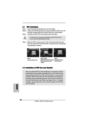
... fits in one correct orientation. Step 3. Then connect the CPU fan to avoid bending of the pins. Step 2. DO NOT force the CPU into the socket to the CPU FAN connector (CPU_FAN1, see Page 12, No. 2). For proper installation, please kindly refer to dissipate heat. The CPU fits only in... heatsink to indicate that it is in good contact with a small triangle. Make sure that the CPU corner with the golden triangle matches the socket corner with each other. When the CPU is necessary to install a larger heatsink and cooling fan to the instruction manuals of CPU Fan and ...
... fits in one correct orientation. Step 3. Then connect the CPU fan to avoid bending of the pins. Step 2. DO NOT force the CPU into the socket to the CPU FAN connector (CPU_FAN1, see Page 12, No. 2). For proper installation, please kindly refer to dissipate heat. The CPU fits only in... heatsink to indicate that it is in good contact with a small triangle. Make sure that the CPU corner with the golden triangle matches the socket corner with each other. When the CPU is necessary to install a larger heatsink and cooling fan to the instruction manuals of CPU Fan and ...
Quick Installation Guide
Page 2
... Power Connector (ATX12V1) 11 NVIDIA GeForce 7050 / nForce 630A MCP 26 CPU Heatsink Retention Module 12 USB 2.0 Header (USB4_5, Blue) 27 AM2 940-Pin CPU Socket 13 Chassis Fan Connector (CHA_FAN1) 28 Print Port Header (LPT1, Purple) 14 Clear CMOS Jumper (CLRCMOS1) 15 Chassis Speaker Header (SPEAKER 1, Purple) 2 ASRock N68PV-GS Motherboard
... Power Connector (ATX12V1) 11 NVIDIA GeForce 7050 / nForce 630A MCP 26 CPU Heatsink Retention Module 12 USB 2.0 Header (USB4_5, Blue) 27 AM2 940-Pin CPU Socket 13 Chassis Fan Connector (CHA_FAN1) 28 Print Port Header (LPT1, Purple) 14 Clear CMOS Jumper (CLRCMOS1) 15 Chassis Speaker Header (SPEAKER 1, Purple) 2 ASRock N68PV-GS Motherboard
Quick Installation Guide
Page 5
...Max. shared memory 256MB (see CAUTION 2) - Supports Blu-ray (BD) / HD-DVD playback up to -Use USB 2.0 Ports 5 ASRock N68PV-GS Motherboard English Supports Untied Overclocking Technology (see CAUTION 6) - Dual VGA Output: support DVI-D and D-Sub ports by independent display controllers - FSB...x PS/2 Keyboard Port - 1 x VGA/D-Sub Port - 1 x VGA/DVI-D Port (see CAUTION 8) - 4 x Ready-to 1080p (see CAUTION 7) - Support for Socket AM2+ / AM2 processors: AMD PhenomTM FX / Phenom / Athlon 64 FX / Athlon 64 X2 Dual-Core / Athlon X2 Dual-Core / Athlon 64 / Sempron processor (see...
...Max. shared memory 256MB (see CAUTION 2) - Supports Blu-ray (BD) / HD-DVD playback up to -Use USB 2.0 Ports 5 ASRock N68PV-GS Motherboard English Supports Untied Overclocking Technology (see CAUTION 6) - Dual VGA Output: support DVI-D and D-Sub ports by independent display controllers - FSB...x PS/2 Keyboard Port - 1 x VGA/D-Sub Port - 1 x VGA/DVI-D Port (see CAUTION 8) - 4 x Ready-to 1080p (see CAUTION 7) - Support for Socket AM2+ / AM2 processors: AMD PhenomTM FX / Phenom / Athlon 64 FX / Athlon 64 X2 Dual-Core / Athlon X2 Dual-Core / Athlon 64 / Sempron processor (see...
Quick Installation Guide
Page 11
..., and/or components. 1. Unplug the power cord from the power supply. Also remember to do so may damage the motherboard. 11 ASRock N68PV-GS Motherboard English Installation This is detached from the wall socket before touching any component, place it . Before you handle components. 3. Doing so may cause severe damage to the chassis, please...
..., and/or components. 1. Unplug the power cord from the power supply. Also remember to do so may damage the motherboard. 11 ASRock N68PV-GS Motherboard English Installation This is detached from the wall socket before touching any component, place it . Before you handle components. 3. Doing so may cause severe damage to the chassis, please...
Quick Installation Guide
Page 12
... 2. Step 3. English 12 ASRock N68PV-GS Motherboard Carefully insert the CPU into the socket to avoid bending of the pins. Step 4. Lever 90° Up STEP 1: Lift Up The Socket Lever CPU Golden Triangle Socker Corner Small Triangle STEP 2 / STEP 3: Match The CPU Golden Triangle To The Socket Corner Small Triangle STEP 4:... the CPU and the heatsink are securely fastened and in place, press it firmly on the side tab to improve heat dissipation. Unlock the socket by lifting the lever up to the CPU FAN connector (CPU_FAN1, see Page 2, No. 2). When the CPU is locked. Position the...
... 2. Step 3. English 12 ASRock N68PV-GS Motherboard Carefully insert the CPU into the socket to avoid bending of the pins. Step 4. Lever 90° Up STEP 1: Lift Up The Socket Lever CPU Golden Triangle Socker Corner Small Triangle STEP 2 / STEP 3: Match The CPU Golden Triangle To The Socket Corner Small Triangle STEP 4:... the CPU and the heatsink are securely fastened and in place, press it firmly on the side tab to improve heat dissipation. Unlock the socket by lifting the lever up to the CPU FAN connector (CPU_FAN1, see Page 2, No. 2). When the CPU is locked. Position the...