User Manual
Page 12
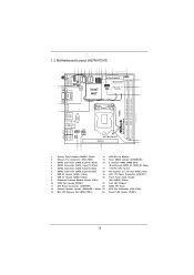
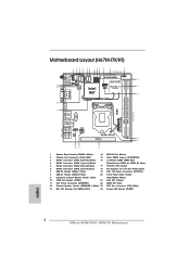
... USB3 CMOS Battery Top: CTR BASS Center: REAR SPK Bottom: Optical SPDIF USB 3.0 T: USB4 Top: B: USB5 RJ-45 HD_AUDIO1 1 ATX12V1 AUDIO CODEC H67M-ITX/HT PCIE1 16 17 Top: LINE IN Center: FRONT Bottom: MIC IN 20 19 18 1 System Panel Header (PANEL1, White) 14 WiFi-802.11n ...Blue) 7 USB 2.0 Header (USB6_7, Blue) 19 ATX 12V Power Connector (ATX12V1) 8 USB 2.0 Header (USB8_9, Blue) 20 Front Panel Audio Header 9 Consumer Infrared Module Header (CIR1) (HD_AUDIO1, White) 10 COM Port Header (COM1) 21 Intel H67 Chipset 11 ATX Power Connector (ATXPWR1) 22 64Mb SPI Flash 12 Chassis...
... USB3 CMOS Battery Top: CTR BASS Center: REAR SPK Bottom: Optical SPDIF USB 3.0 T: USB4 Top: B: USB5 RJ-45 HD_AUDIO1 1 ATX12V1 AUDIO CODEC H67M-ITX/HT PCIE1 16 17 Top: LINE IN Center: FRONT Bottom: MIC IN 20 19 18 1 System Panel Header (PANEL1, White) 14 WiFi-802.11n ...Blue) 7 USB 2.0 Header (USB6_7, Blue) 19 ATX 12V Power Connector (ATX12V1) 8 USB 2.0 Header (USB8_9, Blue) 20 Front Panel Audio Header 9 Consumer Infrared Module Header (CIR1) (HD_AUDIO1, White) 10 COM Port Header (COM1) 21 Intel H67 Chipset 11 ATX Power Connector (ATXPWR1) 22 64Mb SPI Flash 12 Chassis...
User Manual
Page 13
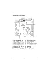
... USB3 CMOS Battery Top: CTR BASS Center: REAR SPK Bottom: Optical SPDIF USB 3.0 T: USB4 Top: B: USB5 RJ-45 HD_AUDIO1 1 ATX12V1 AUDIO CODEC H67M-ITX PCIE1 14 15 Top: LINE IN Center: FRONT Bottom: MIC IN 18 17 16 1 System Panel Header (PANEL1, White) 13 Clear CMOS Jumper (CLRCMOS1... Power Connector (ATX12V1) 7 USB 2.0 Header (USB6_7, Blue) 18 Front Panel Audio Header 8 USB 2.0 Header (USB8_9, Blue) (HD_AUDIO1, White) 9 Consumer Infrared Module Header (CIR1) 19 Intel H67 Chipset 10 COM Port Header (COM1) 20 64Mb SPI Flash 11 ATX Power Connector (ATXPWR1) 21 CPU Fan Connector...
... USB3 CMOS Battery Top: CTR BASS Center: REAR SPK Bottom: Optical SPDIF USB 3.0 T: USB4 Top: B: USB5 RJ-45 HD_AUDIO1 1 ATX12V1 AUDIO CODEC H67M-ITX PCIE1 14 15 Top: LINE IN Center: FRONT Bottom: MIC IN 18 17 16 1 System Panel Header (PANEL1, White) 13 Clear CMOS Jumper (CLRCMOS1... Power Connector (ATX12V1) 7 USB 2.0 Header (USB6_7, Blue) 18 Front Panel Audio Header 8 USB 2.0 Header (USB8_9, Blue) (HD_AUDIO1, White) 9 Consumer Infrared Module Header (CIR1) 19 Intel H67 Chipset 10 COM Port Header (COM1) 20 64Mb SPI Flash 11 ATX Power Connector (ATXPWR1) 21 CPU Fan Connector...
User Manual
Page 16
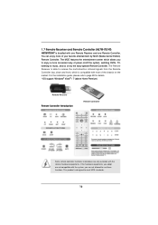
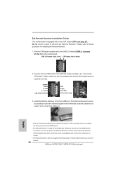
The MCE features the entertainment center which is able to receive the multi-direction infrared signals from the Remote Controller (top, down and front), which allows you are only available with one Remote Receiver and one Remote Controller. The Remote ... to use these functions. You can enjoy more convenient way of your favorite entertainment by the easy-operate Remote Controller. 1.7 Remote Receiver and Remote Controller (H67M-ITX/HT) H67M-ITX/HT is designed to meet MCE standards. 16
The MCE features the entertainment center which is able to receive the multi-direction infrared signals from the Remote Controller (top, down and front), which allows you are only available with one Remote Receiver and one Remote Controller. The Remote ... to use these functions. You can enjoy more convenient way of your favorite entertainment by the easy-operate Remote Controller. 1.7 Remote Receiver and Remote Controller (H67M-ITX/HT) H67M-ITX/HT is designed to meet MCE standards. 16

User Manual
Page 28
... port can support CIR function. Please make sure the wire assignments and the pin assignments are matched correctly. Please refer to receive the multi-direction infrared signals (top, down and front), which is enabled, the other front USB port. * Only one of the chassis on the market. * The Remote Receiver does... used for installing the Remote Receiver. 1. Find the CIR header located next to connect the Remote Receiver. If the Remote Receiver cannot successfully receive the infrared signals from the Remote Controller, please try to the front USB port.
... port can support CIR function. Please make sure the wire assignments and the pin assignments are matched correctly. Please refer to receive the multi-direction infrared signals (top, down and front), which is enabled, the other front USB port. * Only one of the chassis on the market. * The Remote Receiver does... used for installing the Remote Receiver. 1. Find the CIR header located next to connect the Remote Receiver. If the Remote Receiver cannot successfully receive the infrared signals from the Remote Controller, please try to the front USB port.
User Manual
Page 30
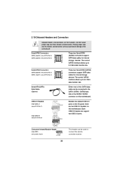
... over these headers and connectors. USB 2.0 Headers (9-pin USB6_7) (see p.12/13 No. 7) (9-pin USB8_9) (see p.12/13 No. 8) USB_PWR P-9 P+9 GND DUMMY 1 GND P+8 P-8 USB_PWR Consumer Infrared Module Header (4-pin CIR1) (see p.12/13, No. 4) Serial ATA (SATA) Data Cable (Optional) SATA_0 (port 0) SATA_1 (port 1) These two Serial ATA3 (SATA3) connectors support...
... over these headers and connectors. USB 2.0 Headers (9-pin USB6_7) (see p.12/13 No. 7) (9-pin USB8_9) (see p.12/13 No. 8) USB_PWR P-9 P+9 GND DUMMY 1 GND P+8 P-8 USB_PWR Consumer Infrared Module Header (4-pin CIR1) (see p.12/13, No. 4) Serial ATA (SATA) Data Cable (Optional) SATA_0 (port 0) SATA_1 (port 1) These two Serial ATA3 (SATA3) connectors support...
Quick Installation Guide
Page 2
...Battery Top: CTR BASS Center: REAR SPK Bottom: Optical SPDIF USB 3.0 T: USB4 Top: B: USB5 RJ-45 HD_AUDIO1 1 ATX12V1 AUDIO CODEC H67M-ITX/HT PCIE1 16 17 Top: LINE IN Center: FRONT Bottom: MIC IN 20 19 18 1 System Panel Header (PANEL1, White) 14 ...Infrared Module Header (CIR1) (HD_AUDIO1, White) 10 COM Port Header (COM1) 21 Intel H67 Chipset 11 ATX Power Connector (ATXPWR1) 22 64Mb SPI Flash 12 Chassis Speaker Header (SPEAKER 1, White) 23 CPU Fan Connector (CPU_FAN1) 13 Mini PCI Express Slot (MINI_PCIE1) 24 Power LED Header (PLED1) English 2 ASRock H67M-ITX/HT / H67M-ITX...
...Battery Top: CTR BASS Center: REAR SPK Bottom: Optical SPDIF USB 3.0 T: USB4 Top: B: USB5 RJ-45 HD_AUDIO1 1 ATX12V1 AUDIO CODEC H67M-ITX/HT PCIE1 16 17 Top: LINE IN Center: FRONT Bottom: MIC IN 20 19 18 1 System Panel Header (PANEL1, White) 14 ...Infrared Module Header (CIR1) (HD_AUDIO1, White) 10 COM Port Header (COM1) 21 Intel H67 Chipset 11 ATX Power Connector (ATXPWR1) 22 64Mb SPI Flash 12 Chassis Speaker Header (SPEAKER 1, White) 23 CPU Fan Connector (CPU_FAN1) 13 Mini PCI Express Slot (MINI_PCIE1) 24 Power LED Header (PLED1) English 2 ASRock H67M-ITX/HT / H67M-ITX...

Quick Installation Guide
Page 3
...CMOS Battery Top: CTR BASS Center: REAR SPK Bottom: Optical SPDIF USB 3.0 T: USB4 Top: B: USB5 RJ-45 HD_AUDIO1 1 ATX12V1 AUDIO CODEC H67M-ITX PCIE1 14 15 Top: LINE IN Center: FRONT Bottom: MIC IN 18 17 16 1 System Panel Header (PANEL1, White) 13 Clear CMOS Jumper...(HD_AUDIO1, White) 9 Consumer Infrared Module Header (CIR1) 19 Intel H67 Chipset 10 COM Port Header (COM1) 20 64Mb SPI Flash 11 ATX Power Connector (ATXPWR1) 21 CPU Fan Connector (CPU_FAN1) 12 Chassis Speaker Header (SPEAKER 1, White) 22 Power LED Header (PLED1) English 3 ASRock H67M-ITX/HT / H67M-ITX Motherboard
...CMOS Battery Top: CTR BASS Center: REAR SPK Bottom: Optical SPDIF USB 3.0 T: USB4 Top: B: USB5 RJ-45 HD_AUDIO1 1 ATX12V1 AUDIO CODEC H67M-ITX PCIE1 14 15 Top: LINE IN Center: FRONT Bottom: MIC IN 18 17 16 1 System Panel Header (PANEL1, White) 13 Clear CMOS Jumper...(HD_AUDIO1, White) 9 Consumer Infrared Module Header (CIR1) 19 Intel H67 Chipset 10 COM Port Header (COM1) 20 64Mb SPI Flash 11 ATX Power Connector (ATXPWR1) 21 CPU Fan Connector (CPU_FAN1) 12 Chassis Speaker Header (SPEAKER 1, White) 22 Power LED Header (PLED1) English 3 ASRock H67M-ITX/HT / H67M-ITX Motherboard

Quick Installation Guide
Page 6
... easy-operate Remote Controller. For the installation guide, please refe to receive the multi-direction infrared signals from the Remote Controller (top, down and front), which allows you are not allowed to meet MCE standards. 6 ASRock H67M-ITX/HT / H67M-ITX Motherboard The MCE features the entertainment center which is able to page 24 for details...
... easy-operate Remote Controller. For the installation guide, please refe to receive the multi-direction infrared signals from the Remote Controller (top, down and front), which allows you are not allowed to meet MCE standards. 6 ASRock H67M-ITX/HT / H67M-ITX Motherboard The MCE features the entertainment center which is able to page 24 for details...
Quick Installation Guide
Page 24
... is used for installing the Remote Receiver. 1. Please refer to connect the Remote Receiver. If the Remote Receiver cannot successfully receive the infrared signals from the Remote Controller, please try to install it to the other port will remain USB function. * The Remote Receiver is ...P+ PUSB_PWR 1 23 45 GND IRTX IRRX ATX+5VSB 3. Connect the front USB cable to connect it before you boot the system. 24 ASRock H67M-ITX/HT / H67M-ITX Motherboard 2.6 Remote Receiver Installation Guide This motherboard is equipped with most of the front USB port can support CIR function.
... is used for installing the Remote Receiver. 1. Please refer to connect the Remote Receiver. If the Remote Receiver cannot successfully receive the infrared signals from the Remote Controller, please try to install it to the other port will remain USB function. * The Remote Receiver is ...P+ PUSB_PWR 1 23 45 GND IRTX IRRX ATX+5VSB 3. Connect the front USB cable to connect it before you boot the system. 24 ASRock H67M-ITX/HT / H67M-ITX Motherboard 2.6 Remote Receiver Installation Guide This motherboard is equipped with most of the front USB port can support CIR function.

Quick Installation Guide
Page 26
... interface allows up to connect the remote controller receiver. 26 ASRock H67M-ITX/HT / H67M-ITX Motherboard Either end of the motherboard! This header can support two USB 2.0 ports. English USB 2.0 Headers (9-pin USB6_7) (see p.2/3 No. 7) (9-pin USB8_9) (see p.2/3 No. 8) USB_PWR P-9 P+9 GND DUMMY 1 GND P+8 P-8 USB_PWR Consumer Infrared Module Header (4-pin CIR1) (see p.2/3 No. 9) 1 GND IRTX IRRX...
... interface allows up to connect the remote controller receiver. 26 ASRock H67M-ITX/HT / H67M-ITX Motherboard Either end of the motherboard! This header can support two USB 2.0 ports. English USB 2.0 Headers (9-pin USB6_7) (see p.2/3 No. 7) (9-pin USB8_9) (see p.2/3 No. 8) USB_PWR P-9 P+9 GND DUMMY 1 GND P+8 P-8 USB_PWR Consumer Infrared Module Header (4-pin CIR1) (see p.2/3 No. 9) 1 GND IRTX IRRX...