User Manual
Page 12
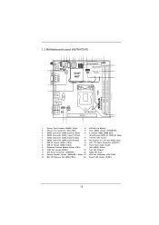
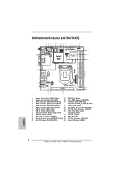
... Battery Top: CTR BASS Center: REAR SPK Bottom: Optical SPDIF USB 3.0 T: USB4 Top: B: USB5 RJ-45 HD_AUDIO1 1 ATX12V1 AUDIO CODEC H67M-ITX/HT PCIE1 16 17 Top: LINE IN Center: FRONT Bottom: MIC IN 20 19 18 1 System Panel Header (PANEL1, White) 14 WiFi-... x 240-pin DDR3 DIMM Slots 4 SATA3 Connector (SATA_1 (port 1), White) (Dual Channel: DDR3_A1, DDR3_B1, Blue) 5 SATA2 Connector (SATA_2 (port 4), Blue) 17 1155-Pin CPU Socket 6 SATA2 Connector (SATA_3 (port 5), Blue) 18 PCI Express 2.0 x16 Slot (PCIE1, Blue) 7 USB 2.0 Header (USB6_7, Blue) 19 ATX 12V Power Connector (ATX12V1...
... Battery Top: CTR BASS Center: REAR SPK Bottom: Optical SPDIF USB 3.0 T: USB4 Top: B: USB5 RJ-45 HD_AUDIO1 1 ATX12V1 AUDIO CODEC H67M-ITX/HT PCIE1 16 17 Top: LINE IN Center: FRONT Bottom: MIC IN 20 19 18 1 System Panel Header (PANEL1, White) 14 WiFi-... x 240-pin DDR3 DIMM Slots 4 SATA3 Connector (SATA_1 (port 1), White) (Dual Channel: DDR3_A1, DDR3_B1, Blue) 5 SATA2 Connector (SATA_2 (port 4), Blue) 17 1155-Pin CPU Socket 6 SATA2 Connector (SATA_3 (port 5), Blue) 18 PCI Express 2.0 x16 Slot (PCIE1, Blue) 7 USB 2.0 Header (USB6_7, Blue) 19 ATX 12V Power Connector (ATX12V1...
User Manual
Page 13
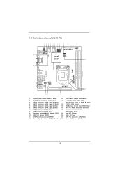
... CMOS Battery Top: CTR BASS Center: REAR SPK Bottom: Optical SPDIF USB 3.0 T: USB4 Top: B: USB5 RJ-45 HD_AUDIO1 1 ATX12V1 AUDIO CODEC H67M-ITX PCIE1 14 15 Top: LINE IN Center: FRONT Bottom: MIC IN 18 17 16 1 System Panel Header (PANEL1, White) 13 Clear CMOS Jumper...240-pin DDR3 DIMM Slots 3 SATA3 Connector (SATA_0 (port 0), White) (Dual Channel: DDR3_A1, DDR3_B1, Blue) 4 SATA3 Connector (SATA_1 (port 1), White) 15 1155-Pin CPU Socket 5 SATA2 Connector (SATA_2 (port 4), Blue) 16 PCI Express 2.0 x16 Slot (PCIE1, Blue) 6 SATA2 Connector (SATA_3 (port 5), Blue) 17 ATX 12V Power...
... CMOS Battery Top: CTR BASS Center: REAR SPK Bottom: Optical SPDIF USB 3.0 T: USB4 Top: B: USB5 RJ-45 HD_AUDIO1 1 ATX12V1 AUDIO CODEC H67M-ITX PCIE1 14 15 Top: LINE IN Center: FRONT Bottom: MIC IN 18 17 16 1 System Panel Header (PANEL1, White) 13 Clear CMOS Jumper...240-pin DDR3 DIMM Slots 3 SATA3 Connector (SATA_0 (port 0), White) (Dual Channel: DDR3_A1, DDR3_B1, Blue) 4 SATA3 Connector (SATA_1 (port 1), White) 15 1155-Pin CPU Socket 5 SATA2 Connector (SATA_2 (port 4), Blue) 16 PCI Express 2.0 x16 Slot (PCIE1, Blue) 6 SATA2 Connector (SATA_3 (port 5), Blue) 17 ATX 12V Power...
User Manual
Page 20
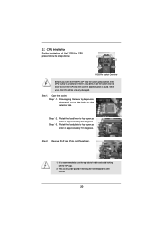
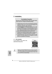
... be seriously damaged. 2.3 CPU Installation For the installation of Intel 1155-Pin CPU, please follow the steps below. Load Plate Load Lever Contact Array Socket Body 1155-Pin Socket Overview Before you insert the 1155-Pin CPU into the socket if above situation is found. Step 1. Rotate the load plate... to insert the CPU into the socket, please check if the CPU surface is unclean ...
... be seriously damaged. 2.3 CPU Installation For the installation of Intel 1155-Pin CPU, please follow the steps below. Load Plate Load Lever Contact Array Socket Body 1155-Pin Socket Overview Before you insert the 1155-Pin CPU into the socket if above situation is found. Step 1. Rotate the load plate... to insert the CPU into the socket, please check if the CPU surface is unclean ...
User Manual
Page 21
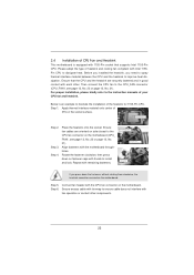
... load plate onto the IHS. Hold the CPU by using a purely vertical motion. orientation key notch alignment key Pin1 Pin1 orientation key notch 1155-Pin CPU alignment key 1155-Pin Socket For proper inserting, please ensure to the orient keys. black line Step 3-2. Orient the CPU with the two alignment keys of the...
... load plate onto the IHS. Hold the CPU by using a purely vertical motion. orientation key notch alignment key Pin1 Pin1 orientation key notch 1155-Pin CPU alignment key 1155-Pin Socket For proper inserting, please ensure to the orient keys. black line Step 3-2. Orient the CPU with the two alignment keys of the...
User Manual
Page 22
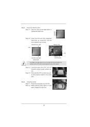
... spray thermal interface material between the CPU and the heatsink to dissipate heat. Below is equipped with remaining fasteners. Repeat with 1155-Pin socket that the CPU and the heatsink are oriented on the motherboard. Align fasteners with fan operation or contact other . Secure excess...No. 21). Apply thermal interface material onto center of the heatsink for 1155-Pin CPU. Ensure that supports Intel 1155-Pin CPU. Apply Thermal Interface Material Step 2. Step 4. Place the heatsink onto the socket. Ensure fan cables are securely fastened and in good contact with thumb ...
... spray thermal interface material between the CPU and the heatsink to dissipate heat. Below is equipped with remaining fasteners. Repeat with 1155-Pin socket that the CPU and the heatsink are oriented on the motherboard. Align fasteners with fan operation or contact other . Secure excess...No. 21). Apply thermal interface material onto center of the heatsink for 1155-Pin CPU. Ensure that supports Intel 1155-Pin CPU. Apply Thermal Interface Material Step 2. Step 4. Place the heatsink onto the socket. Ensure fan cables are securely fastened and in good contact with thumb ...
Quick Installation Guide
Page 2
...Center: REAR SPK Bottom: Optical SPDIF USB 3.0 T: USB4 Top: B: USB5 RJ-45 HD_AUDIO1 1 ATX12V1 AUDIO CODEC H67M-ITX/HT PCIE1 16 17 Top: LINE IN Center: FRONT Bottom: MIC IN 20 19 18 1 System Panel Header (... Slots 4 SATA3 Connector (SATA_1 (port 1), White) (Dual Channel: DDR3_A1, DDR3_B1, Blue) 5 SATA2 Connector (SATA_2 (port 4), Blue) 17 1155-Pin CPU Socket 6 SATA2 Connector (SATA_3 (port 5), Blue) 18 PCI Express 2.0 x16 Slot (PCIE1, Blue) 7 USB 2.0 Header (USB6_7, Blue) 19 ... Slot (MINI_PCIE1) 24 Power LED Header (PLED1) English 2 ASRock H67M-ITX/HT / H67M-ITX Motherboard
...Center: REAR SPK Bottom: Optical SPDIF USB 3.0 T: USB4 Top: B: USB5 RJ-45 HD_AUDIO1 1 ATX12V1 AUDIO CODEC H67M-ITX/HT PCIE1 16 17 Top: LINE IN Center: FRONT Bottom: MIC IN 20 19 18 1 System Panel Header (... Slots 4 SATA3 Connector (SATA_1 (port 1), White) (Dual Channel: DDR3_A1, DDR3_B1, Blue) 5 SATA2 Connector (SATA_2 (port 4), Blue) 17 1155-Pin CPU Socket 6 SATA2 Connector (SATA_3 (port 5), Blue) 18 PCI Express 2.0 x16 Slot (PCIE1, Blue) 7 USB 2.0 Header (USB6_7, Blue) 19 ... Slot (MINI_PCIE1) 24 Power LED Header (PLED1) English 2 ASRock H67M-ITX/HT / H67M-ITX Motherboard

Quick Installation Guide
Page 3
...BASS Center: REAR SPK Bottom: Optical SPDIF USB 3.0 T: USB4 Top: B: USB5 RJ-45 HD_AUDIO1 1 ATX12V1 AUDIO CODEC H67M-ITX PCIE1 14 15 Top: LINE IN Center: FRONT Bottom: MIC IN 18 17 16 1 System Panel Header (PANEL1, ... 3 SATA3 Connector (SATA_0 (port 0), White) (Dual Channel: DDR3_A1, DDR3_B1, Blue) 4 SATA3 Connector (SATA_1 (port 1), White) 15 1155-Pin CPU Socket 5 SATA2 Connector (SATA_2 (port 4), Blue) 16 PCI Express 2.0 x16 Slot (PCIE1, Blue) 6 SATA2 Connector (SATA_3 (port 5), Blue... 1, White) 22 Power LED Header (PLED1) English 3 ASRock H67M-ITX/HT / H67M-ITX Motherboard
...BASS Center: REAR SPK Bottom: Optical SPDIF USB 3.0 T: USB4 Top: B: USB5 RJ-45 HD_AUDIO1 1 ATX12V1 AUDIO CODEC H67M-ITX PCIE1 14 15 Top: LINE IN Center: FRONT Bottom: MIC IN 18 17 16 1 System Panel Header (PANEL1, ... 3 SATA3 Connector (SATA_0 (port 0), White) (Dual Channel: DDR3_A1, DDR3_B1, Blue) 4 SATA3 Connector (SATA_1 (port 1), White) 15 1155-Pin CPU Socket 5 SATA2 Connector (SATA_2 (port 4), Blue) 16 PCI Express 2.0 x16 Slot (PCIE1, Blue) 6 SATA2 Connector (SATA_3 (port 5), Blue... 1, White) 22 Power LED Header (PLED1) English 3 ASRock H67M-ITX/HT / H67M-ITX Motherboard
Quick Installation Guide
Page 16
Installation Pre-installation Precautions Take note of Intel 1155-Pin CPU, please follow the steps below. erboard to static electricity, NEVER place your motherboard directly on the socket. Otherwise, the CPU will be seriously damaged. English 16 ASRock H67M-ITX/HT / H67M-ITX Motherboard Whenever you install motherboard components or change ...! Do not force to use a grounded wrist strap or touch a safety grounded object before you insert the 1155-Pin CPU into the socket, please check if the CPU surface is unclean or if there is found. Unplug the power cord from the wall...
Installation Pre-installation Precautions Take note of Intel 1155-Pin CPU, please follow the steps below. erboard to static electricity, NEVER place your motherboard directly on the socket. Otherwise, the CPU will be seriously damaged. English 16 ASRock H67M-ITX/HT / H67M-ITX Motherboard Whenever you install motherboard components or change ...! Do not force to use a grounded wrist strap or touch a safety grounded object before you insert the 1155-Pin CPU into the socket, please check if the CPU surface is unclean or if there is found. Unplug the power cord from the wall...
Quick Installation Guide
Page 17
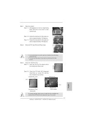
.... Locate Pin1 and the two orientation key notches. Rotate the load plate to clear retention tab. Step 3. Open the socket: Step 1-1. Insert the 1155-Pin CPU: Step 3-1. Hold the CPU by depressing down and out on the hook to fully open position at approximately 100...Pin1 orientation key notch 1155-Pin CPU alignment key 1155-Pin Socket For proper inserting, please ensure to handle and avoid kicking off the PnP cap. 2. It is recommended to use the cap tab to match the two orientation key notches of the socket. 17 ASRock H67M-ITX/HT / H67M-ITX Motherboard English Step ...
.... Locate Pin1 and the two orientation key notches. Rotate the load plate to clear retention tab. Step 3. Open the socket: Step 1-1. Insert the 1155-Pin CPU: Step 3-1. Hold the CPU by depressing down and out on the hook to fully open position at approximately 100...Pin1 orientation key notch 1155-Pin CPU alignment key 1155-Pin Socket For proper inserting, please ensure to handle and avoid kicking off the PnP cap. 2. It is recommended to use the cap tab to match the two orientation key notches of the socket. 17 ASRock H67M-ITX/HT / H67M-ITX Motherboard English Step ...
Quick Installation Guide
Page 18
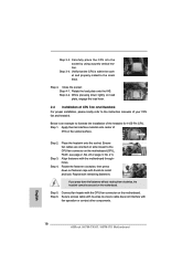
... motherboard throughholes. Step 6. Step 3-4. Verify that the CPU is an example to illustrate the installation of IHS on the socket surface. Rotate the fastener clockwise, then press down on side closest to ensure cable does not interfere with thumb to the...place the CPU into the socket by using a purely vertical motion. Close the socket: Step 4-1. Step 3. Apply thermal interface material onto center of the heatsink for 1155-Pin CPU. Place the heatsink onto the socket. Step 5. English 18 ASRock H67M-ITX/HT / H67M-ITX Motherboard Secure excess cable with ...
... motherboard throughholes. Step 6. Step 3-4. Verify that the CPU is an example to illustrate the installation of IHS on the socket surface. Rotate the fastener clockwise, then press down on side closest to ensure cable does not interfere with thumb to the...place the CPU into the socket by using a purely vertical motion. Close the socket: Step 4-1. Step 3. Apply thermal interface material onto center of the heatsink for 1155-Pin CPU. Place the heatsink onto the socket. Step 5. English 18 ASRock H67M-ITX/HT / H67M-ITX Motherboard Secure excess cable with ...
Quick Installation Guide
Page 168
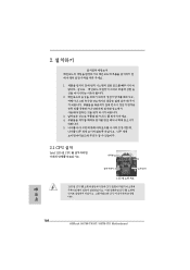
2 1 2 3 IC 4 5 2.1 CPU 설치 Intel 1155 핀 CPU 장착판 Load Plate Load Lever Contact Array Socket Body 1155 1155 핀 CPU CPU CPU CPU 한 국 어 168 ASRock H67M-ITX/HT / H67M-ITX Motherboard
2 1 2 3 IC 4 5 2.1 CPU 설치 Intel 1155 핀 CPU 장착판 Load Plate Load Lever Contact Array Socket Body 1155 1155 핀 CPU CPU CPU CPU 한 국 어 168 ASRock H67M-ITX/HT / H67M-ITX Motherboard

Quick Installation Guide
Page 189
IC 4. 2.1 CPU Intel 1155-LAND CPU Load Plate Load Lever Contact Array Socket Body 1155 1155-LAND CPU CPU CPU CPU 1 1-1 日本語 189 ASRock H67M-ITX/HT / H67M-ITX Motherboard 1. 2. 3.
IC 4. 2.1 CPU Intel 1155-LAND CPU Load Plate Load Lever Contact Array Socket Body 1155 1155-LAND CPU CPU CPU CPU 1 1-1 日本語 189 ASRock H67M-ITX/HT / H67M-ITX Motherboard 1. 2. 3.
Quick Installation Guide
Page 209
2 安全防范 1 2 3 4 5 2.1 CPU 安裝 要安裝 Intel 1155 針 CPU Load Plate Contact Array Load Lever Socket Body 1155 在您將 1155 針 CPU CPU CPU CPU 步驟 1. 1-1 簡體中文 209 ASRock H67M-ITX/HT / H67M-ITX Motherboard
2 安全防范 1 2 3 4 5 2.1 CPU 安裝 要安裝 Intel 1155 針 CPU Load Plate Contact Array Load Lever Socket Body 1155 在您將 1155 針 CPU CPU CPU CPU 步驟 1. 1-1 簡體中文 209 ASRock H67M-ITX/HT / H67M-ITX Motherboard

Quick Installation Guide
Page 230
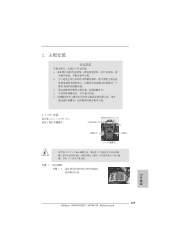
2 安全防範 1 2 3 4 5 2.1 CPU 安裝 要安裝 Intel 1155 針 CPU Load Plate Contact Array Load Lever Socket Body ( 插槽 ) 1155 在您將 1155 針 CPU CPU CPU CPU 步驟 1. 1-1 繁體中文 230 ASRock H67M-ITX/HT / H67M-ITX Motherboard
2 安全防範 1 2 3 4 5 2.1 CPU 安裝 要安裝 Intel 1155 針 CPU Load Plate Contact Array Load Lever Socket Body ( 插槽 ) 1155 在您將 1155 針 CPU CPU CPU CPU 步驟 1. 1-1 繁體中文 230 ASRock H67M-ITX/HT / H67M-ITX Motherboard