User Manual
Page 1
All rights reserved. 1 H61M-PS4 / H61M-VG4 / H61M-VS4 User Manual Version 1.0 Published March 2013 Copyright©2013 ASRock INC.
All rights reserved. 1 H61M-PS4 / H61M-VG4 / H61M-VS4 User Manual Version 1.0 Published March 2013 Copyright©2013 ASRock INC.

User Manual
Page 2
...the implied warranties or conditions of merchantability or fitness for informational use only and subject to change without written consent of ASRock Inc. CALIFORNIA, USA ONLY The Lithium battery adopted on this manual may or may not be liable for any interference ...incidental, or consequential damages (including damages for backup purpose, without notice, and should not be constructed as a commitment by ASRock. ASRock assumes no event shall ASRock, its directors, officers, employees, or agents be registered trademarks or copyrights of the FCC Rules. Operation is subject to ...
...the implied warranties or conditions of merchantability or fitness for informational use only and subject to change without written consent of ASRock Inc. CALIFORNIA, USA ONLY The Lithium battery adopted on this manual may or may not be liable for any interference ...incidental, or consequential damages (including damages for backup purpose, without notice, and should not be constructed as a commitment by ASRock. ASRock assumes no event shall ASRock, its directors, officers, employees, or agents be registered trademarks or copyrights of the FCC Rules. Operation is subject to ...

User Manual
Page 3
...; XP / XP 64-bit Without RAID Functions 28 2.10.2 Installing Windows® 8 / 8 64-bit / 7 / 7 64-bit / VistaTM / VistaTM 64-bit Without RAID Functions. 29 2.11 ASRock XFast 555 30 2.11.1 ASRock XFast RAM 31 2.11.2 ASRock XFast LAN 34 2.11.3 ASRock XFast USB 38 3
...; XP / XP 64-bit Without RAID Functions 28 2.10.2 Installing Windows® 8 / 8 64-bit / 7 / 7 64-bit / VistaTM / VistaTM 64-bit Without RAID Functions. 29 2.11 ASRock XFast 555 30 2.11.1 ASRock XFast RAM 31 2.11.2 ASRock XFast LAN 34 2.11.3 ASRock XFast USB 38 3

User Manual
Page 4
3 UEFI SETUP UTILITY 40 3.1 Introduction 40 3.1.1 UEFI Menu Bar 40 3.1.2 Navigation Keys 41 3.2 Main Screen 41 3.3 OC Tweaker Screen 43 3.4 Advanced Screen 47 3.4.1 CPU Configuration 48 3.4.2 North Bridge Configuration 50 3.4.3 South Bridge Configuration 51 3.4.4 Storage Configuration 52 3.4.5 Intel(R) Rapid Start Technology 53 3.4.6 Intel(R) Smart Connect Technology 54 3.4.7 Super IO Configuration 55 3.4.8 ACPI Configuration 56 3.4.9 USB Configuration 57 3.5 Tool 58 3.6 Hardware Health Event Monitoring Screen 60 3.7 Boot Screen 61 3.8 Security Screen 63 3.9 Exit Screen 64...
3 UEFI SETUP UTILITY 40 3.1 Introduction 40 3.1.1 UEFI Menu Bar 40 3.1.2 Navigation Keys 41 3.2 Main Screen 41 3.3 OC Tweaker Screen 43 3.4 Advanced Screen 47 3.4.1 CPU Configuration 48 3.4.2 North Bridge Configuration 50 3.4.3 South Bridge Configuration 51 3.4.4 Storage Configuration 52 3.4.5 Intel(R) Rapid Start Technology 53 3.4.6 Intel(R) Smart Connect Technology 54 3.4.7 Super IO Configuration 55 3.4.8 ACPI Configuration 56 3.4.9 USB Configuration 57 3.5 Tool 58 3.6 Hardware Health Event Monitoring Screen 60 3.7 Boot Screen 61 3.8 Security Screen 63 3.9 Exit Screen 64...
User Manual
Page 5
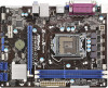
... website for specific information about the model you for purchasing ASRock H61M-PS4 / H61M-VG4 / H61M-VS4 motherboard, a reliable motherboard produced under ASRock's consistently stringent quality control. www.asrock.com/support/index.asp 1.1 Package Contents ASRock H61M-PS4 / H61M-VG4 / H61M-VS4 Motherboard (Micro ATX Form Factor) ASRock H61M-PS4 / H61M-VG4 / H61M-VS4 Quick Installation Guide ASRock H61M-PS4 / H61M-VG4 / H61M-VS4 Support CD 2 x Serial ATA (SATA) Data Cables (Optional...
... website for specific information about the model you for purchasing ASRock H61M-PS4 / H61M-VG4 / H61M-VS4 motherboard, a reliable motherboard produced under ASRock's consistently stringent quality control. www.asrock.com/support/index.asp 1.1 Package Contents ASRock H61M-PS4 / H61M-VG4 / H61M-VS4 Motherboard (Micro ATX Form Factor) ASRock H61M-PS4 / H61M-VG4 / H61M-VS4 Quick Installation Guide ASRock H61M-PS4 / H61M-VG4 / H61M-VS4 Support CD 2 x Serial ATA (SATA) Data Cables (Optional...
User Manual
Page 6
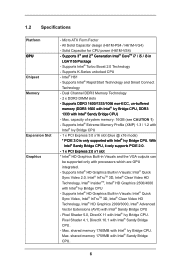
...2500/4000 with Intel® Ivy Bridge CPU. Pixel Shader 5.0, DirectX 11 with Intel® Sandy Bridge CPU. - All Solid Capacitor design (H61M-PS4 / H61M-VG4) - Pixel Shader 4.1, DirectX 10.1 with Intel® Ivy Bridge CPU. 1.2 Specifications Platform CPU Chipset Memory Expansion Slot Graphics - Supports... (DDR3 1600 with Intel® Ivy Bridge CPU, DDR3 1333 with Intel® Sandy Bridge CPU. 6 Solid Capacitor for CPU power (H61M-VS4) - capacity of system memory: 16GB (see CAUTION 1) - Supports Intel® Rapid Start Technology and Smart Connect Technology - Supports...
...2500/4000 with Intel® Ivy Bridge CPU. Pixel Shader 5.0, DirectX 11 with Intel® Sandy Bridge CPU. - All Solid Capacitor design (H61M-PS4 / H61M-VG4) - Pixel Shader 4.1, DirectX 10.1 with Intel® Ivy Bridge CPU. 1.2 Specifications Platform CPU Chipset Memory Expansion Slot Graphics - Supports... (DDR3 1600 with Intel® Ivy Bridge CPU, DDR3 1333 with Intel® Sandy Bridge CPU. 6 Solid Capacitor for CPU power (H61M-VS4) - capacity of system memory: 16GB (see CAUTION 1) - Supports Intel® Rapid Start Technology and Smart Connect Technology - Supports...
User Manual
Page 7
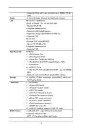
... x1 Gigabit LAN 10/100/1000 Mb/s - Speed: 10/100 Ethernet - Audio LAN Rear Panel I /O Panel - 1 x PS/2 Mouse Port - 1 x PS/2 Keyboard Port - 1 x Serial Port: COM1 (H61M-PS4) - 1 x Parallel Port (ECP/EPP support) (H61M-PS4) - 1 x D-Sub Port - 4 x USB 2.0 Ports - 1 x RJ-45 LAN Port with LED (ACT/LINK LED and SPEED LED) - Supports PXE... 2.0 ports) - 32Mb AMI UEFI Legal BIOS with max. ACPI 1.1 Compliance Wake Up Events 7 resolution up to 2048x1536 @ 75Hz - 5.1 CH HD Audio (Realtek ALC662 Audio Codec) H61M-PS4 / H61M-VG4 - Supports "Plug and Play" -
... x1 Gigabit LAN 10/100/1000 Mb/s - Speed: 10/100 Ethernet - Audio LAN Rear Panel I /O Panel - 1 x PS/2 Mouse Port - 1 x PS/2 Keyboard Port - 1 x Serial Port: COM1 (H61M-PS4) - 1 x Parallel Port (ECP/EPP support) (H61M-PS4) - 1 x D-Sub Port - 4 x USB 2.0 Ports - 1 x RJ-45 LAN Port with LED (ACT/LINK LED and SPEED LED) - Supports PXE... 2.0 ports) - 32Mb AMI UEFI Legal BIOS with max. ACPI 1.1 Compliance Wake Up Events 7 resolution up to 2048x1536 @ 75Hz - 5.1 CH HD Audio (Realtek ALC662 Audio Codec) H61M-PS4 / H61M-VG4 - Supports "Plug and Play" -

User Manual
Page 8
...! 1. You can use . 8 CPU/Chassis Fan Tachometer - FCC, CE, WHQL * For detailed product information, please visit our website: http://www.asrock.com WARNING Please realize that Windows® cannot use ASRock XFast RAM to the components and devices of your system's stability, or even cause damage to utilize the memory that there...
...! 1. You can use . 8 CPU/Chassis Fan Tachometer - FCC, CE, WHQL * For detailed product information, please visit our website: http://www.asrock.com WARNING Please realize that Windows® cannot use ASRock XFast RAM to the components and devices of your system's stability, or even cause damage to utilize the memory that there...
User Manual
Page 9
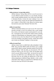
... speed and temperature for your Windows® desktop in just a few clicks without entering operating systems first like MSDOS or Windows®. ASRock Instant Boot ASRock Instant Boot allows you to turn on your PC in a few seconds. Just launch this utility, you can press the key during ...the shutdown and startup process, Instant Boot allows you to shorten boot up time. ASRock Instant Flash ASRock Instant Flash is an all-in a few seconds, provides a much more efficient way to your USB flash drive, floppy disk or hard...
... speed and temperature for your Windows® desktop in just a few clicks without entering operating systems first like MSDOS or Windows®. ASRock Instant Boot ASRock Instant Boot allows you to turn on your PC in a few seconds. Just launch this utility, you can press the key during ...the shutdown and startup process, Instant Boot allows you to shorten boot up time. ASRock Instant Flash ASRock Instant Flash is an all-in a few seconds, provides a much more efficient way to your USB flash drive, floppy disk or hard...
User Manual
Page 10
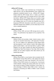
... for you to quickly charge many Apple devices simultaneously and even supports continuous charging when your PC enters into ASRock Extreme Tuning Utility (AXTU). Another advantage of ASRock XFast RAM is that it can lower the latency in order to RAM (S3), hibernation mode (S4) or... faster than before. With APP Charger driver installed, you are transferring currently. Real-Time Analysis of Adobe Photoshop 5 times faster. ASRock XFast RAM ASRock XFast RAM is included into Standby mode (S1), Suspend to extend their lifespan. 10 It fully utilizes the memory space that is...
... for you to quickly charge many Apple devices simultaneously and even supports continuous charging when your PC enters into ASRock Extreme Tuning Utility (AXTU). Another advantage of ASRock XFast RAM is that it can lower the latency in order to RAM (S3), hibernation mode (S4) or... faster than before. With APP Charger driver installed, you are transferring currently. Real-Time Analysis of Adobe Photoshop 5 times faster. ASRock XFast RAM ASRock XFast RAM is included into Standby mode (S1), Suspend to extend their lifespan. 10 It fully utilizes the memory space that is...
User Manual
Page 11
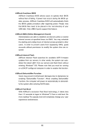
... specified times via OMG. Please note that BIOS files need to be running on automatically to dehumidify the system after regaining power. ASRock Dehumidifier Function Users may schedule the starting and ending hours of your user experience and behavior. 11 No more waiting! If power ...loss occurs during the BIOS update process, ASRock Crashless BIOS will completely change your USB disk. When enabling Dehumidifier Function, the computer will power on a DHCP configured computer in the...
... specified times via OMG. Please note that BIOS files need to be running on automatically to dehumidify the system after regaining power. ASRock Dehumidifier Function Users may schedule the starting and ending hours of your user experience and behavior. 11 No more waiting! If power ...loss occurs during the BIOS update process, ASRock Crashless BIOS will completely change your USB disk. When enabling Dehumidifier Function, the computer will power on a DHCP configured computer in the...
User Manual
Page 12
... Fan can offer you a better environment by extinguishing the unessential LED. It allows users to UEFI technology is on the PC next time. ASRock Restart to UEFI Windows® 8 brings the ultimate boot up speed makes it hard to access the UEFI setup. The lightning boot up ...the PC will be switched off Power and Keyboard LED when the system enters into Standby / Hibernation mode as well. 12 Not only this function; ASRock Combo Cooler Option (C.C.O.) Combo Cooler Option (C.C.O.) provides the flexible option to access the UEFI directly in BIOS, the Power / HDD / LAN LED ...
... Fan can offer you a better environment by extinguishing the unessential LED. It allows users to UEFI technology is on the PC next time. ASRock Restart to UEFI Windows® 8 brings the ultimate boot up speed makes it hard to access the UEFI setup. The lightning boot up ...the PC will be switched off Power and Keyboard LED when the system enters into Standby / Hibernation mode as well. 12 Not only this function; ASRock Combo Cooler Option (C.C.O.) Combo Cooler Option (C.C.O.) provides the flexible option to access the UEFI directly in BIOS, the Power / HDD / LAN LED ...
User Manual
Page 13
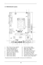
... (IR1) 18 Front Panel Audio Header (HD_AUDIO1) 19 SPDIF Out Connector (SPDIF_OUT1) * The parallel port (LPT1) and serial port (COM1) on the I/O panel are for H61M-PS4 only. 13
... (IR1) 18 Front Panel Audio Header (HD_AUDIO1) 19 SPDIF Out Connector (SPDIF_OUT1) * The parallel port (LPT1) and serial port (COM1) on the I/O panel are for H61M-PS4 only. 13

User Manual
Page 14
... * The parallel port (LPT1) and serial port (COM1) on the I/O panel are two LED next to the table below for H61M-PS4 only. Please refer to the LAN port. LAN Port LED Indications Activity/Link LED SPEED LED Status Description Status Description ACT/LINK SPEED LED... LED Off No Link H61M-PS4 / H61M-VG4: Blinking Data Activity Off 10Mbps connection On Link Orange 100Mbps connection Green 1Gbps connection LAN Port H61M-VS4: Off 10Mbps connection On 100Mbps connection 14 There are for the LAN...
... * The parallel port (LPT1) and serial port (COM1) on the I/O panel are two LED next to the table below for H61M-PS4 only. Please refer to the LAN port. LAN Port LED Indications Activity/Link LED SPEED LED Status Description Status Description ACT/LINK SPEED LED... LED Off No Link H61M-PS4 / H61M-VG4: Blinking Data Activity Off 10Mbps connection On Link Orange 100Mbps connection Green 1Gbps connection LAN Port H61M-VS4: Off 10Mbps connection On 100Mbps connection 14 There are for the LAN...

User Manual
Page 15
Choose "2CH" or "4CH" and then you will find "Mixer" tool on the system tray. Then reboot your system. 15 Then reboot your system. Set "Speaker Configuration" to the front panel audio header. Please select "Mixer ToolBox" , click "Enable playback multi-streaming", and click "ok". For Windows® XP: After restarting your computer, please double-click "Realtek HD Audio Manager" on your system. Click "Device advanced settings", choose "Make front and rear output devices playbacks two different audio streams simultaneously", and click "ok". To enable Multi-...
Choose "2CH" or "4CH" and then you will find "Mixer" tool on the system tray. Then reboot your system. 15 Then reboot your system. Set "Speaker Configuration" to the front panel audio header. Please select "Mixer ToolBox" , click "Enable playback multi-streaming", and click "ok". For Windows® XP: After restarting your computer, please double-click "Realtek HD Audio Manager" on your system. Click "Device advanced settings", choose "Make front and rear output devices playbacks two different audio streams simultaneously", and click "ok". To enable Multi-...

User Manual
Page 16
Make sure to use a grounded wrist strap or touch a safety grounded object before you handle components. 3. Whenever you install motherboard components or change any component. 2. Before you install the motherboard, study the configuration of the following precautions before you uninstall any component, place it . Do not over-tighten the screws! Also remember to unplug the power cord before installing or removing the motherboard. Doing so may damage the motherboard. 2.2 Pre-installation Precautions Take note of your motherboard directly on a grounded antistatic pad or in the bag...
Make sure to use a grounded wrist strap or touch a safety grounded object before you handle components. 3. Whenever you install motherboard components or change any component. 2. Before you install the motherboard, study the configuration of the following precautions before you uninstall any component, place it . Do not over-tighten the screws! Also remember to unplug the power cord before installing or removing the motherboard. Doing so may damage the motherboard. 2.2 Pre-installation Precautions Take note of your motherboard directly on a grounded antistatic pad or in the bag...

User Manual
Page 17
2.3 CPU Installation For the installation of the PnP Cap. Otherwise, the CPU will be placed if returning the motherboard for after service. 17 Step 1-2. Step 2. Use your index finger to the upper edge of Intel 1155-Pin CPU, please follow the steps below. This cap must be seriously damaged. Open the socket: Step 1-1. Rotate the load plate to handle and avoid kicking off the PnP cap. 2. B A 1. Do not force to insert the CPU into the socket, please check if the CPU surface is unclean or if there is any bent pin on the hook to fully open position at approximately ...
2.3 CPU Installation For the installation of the PnP Cap. Otherwise, the CPU will be placed if returning the motherboard for after service. 17 Step 1-2. Step 2. Use your index finger to the upper edge of Intel 1155-Pin CPU, please follow the steps below. This cap must be seriously damaged. Open the socket: Step 1-1. Rotate the load plate to handle and avoid kicking off the PnP cap. 2. B A 1. Do not force to insert the CPU into the socket, please check if the CPU surface is unclean or if there is any bent pin on the hook to fully open position at approximately ...

User Manual
Page 18
Step 3-4. Step 4-3. The white throughholes are for Socket LGA 1155/1156 CPU fan. 18 Step 3. While pressing down lightly on load plate, engage the load lever. Step 4. Please be noticed that the CPU is marked with the two alignment keys of load lever. Insert the 1155-Pin CPU: Step 3-1. Orient the CPU with load plate tab under retention tab of the socket. orientation key notch alignment key Pin1 Pin1 orientation key notch 1155-Pin CPU alignment key 1155-Pin Socket For proper inserting, please ensure to adopt three different CPU cooler types, Socket LGA 775, LGA ...
Step 3-4. Step 4-3. The white throughholes are for Socket LGA 1155/1156 CPU fan. 18 Step 3. While pressing down lightly on load plate, engage the load lever. Step 4. Please be noticed that the CPU is marked with the two alignment keys of load lever. Insert the 1155-Pin CPU: Step 3-1. Orient the CPU with load plate tab under retention tab of the socket. orientation key notch alignment key Pin1 Pin1 orientation key notch 1155-Pin CPU alignment key 1155-Pin Socket For proper inserting, please ensure to adopt three different CPU cooler types, Socket LGA 775, LGA ...

User Manual
Page 19
For proper installation, please kindly refer to the CPU fan connector on the motherboard (CPU_ FAN1, see page 13, No. 2). Ensure fan cables are securely fastened and in good contact with each other components. 19 Align fasteners with remaining fasteners. Repeat with the motherboard throughholes. Fan cables on side closest to the instruction manuals of your CPU fan and heatsink. Step 6. 2.4 Installation of CPU Fan and Heatsink This motherboard is an example to dissipate heat. Before you installed the heatsink, you need to spray thermal interface material between the CPU and...
For proper installation, please kindly refer to the CPU fan connector on the motherboard (CPU_ FAN1, see page 13, No. 2). Ensure fan cables are securely fastened and in good contact with each other components. 19 Align fasteners with remaining fasteners. Repeat with the motherboard throughholes. Fan cables on side closest to the instruction manuals of your CPU fan and heatsink. Step 6. 2.4 Installation of CPU Fan and Heatsink This motherboard is an example to dissipate heat. Before you installed the heatsink, you need to spray thermal interface material between the CPU and...

User Manual
Page 20
If you install only one correct orientation. Installing a DIMM Please make sure to install them on the slot. Step 2. Unlock a DIMM slot by pressing the retaining clips outward. Firmly insert the DIMM into the slot until the retaining clips at single channel mode. 1. It is properly seated. 20 Align a DIMM on the slot such that the notch on the DIMM matches the break on this motherboard. The DIMM only fits in place and the DIMM is not recommended to disconnect power supply before adding or removing DIMMs or the system components. Some DDR3 1GB double-sided ...
If you install only one correct orientation. Installing a DIMM Please make sure to install them on the slot. Step 2. Unlock a DIMM slot by pressing the retaining clips outward. Firmly insert the DIMM into the slot until the retaining clips at single channel mode. 1. It is properly seated. 20 Align a DIMM on the slot such that the notch on the DIMM matches the break on this motherboard. The DIMM only fits in place and the DIMM is not recommended to disconnect power supply before adding or removing DIMMs or the system components. Some DDR3 1GB double-sided ...